Intake Manifold Assembly Overview
Intake Manifold Assembly Overview
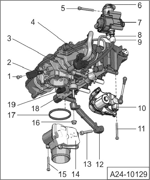
1 - Intake Air Temperature (IAT) Sensor 2 (G299) bolt
• 5 Nm
2 - Intake Air Temperature (IAT) Sensor 2 (G299)
3 - Intake manifold
• Removing and installing, refer to => [ Intake Manifold with Fuel Rail ] Intake Manifold With Fuel Rail
• The intake manifold runner position sensor (G336 ) item 10 must be adapted to the engine control module (J623) after removing or replacing the intake manifold vehicle diagnosis, testing and information system (VAS 5052 ) "Guided Function".
4 - Evaporative Emission (EVAP) Canister Purge Regulator Valve (N80)
5 - Bolt for single-piston high-pressure pump
• 3 pieces
• 10 Nm
6 - Fuel Pressure Regulator Valve (N276)
7 - Mechanical single-piston high-pressure pump
• With Fuel Pressure Regulator Valve (N276) and Low Fuel Pressure Sensor (G410)
• An electrical fuel pump, located in the fuel tank, supplies fuel to the mechanical high-pressure pump at a pressure of approximately 6 bar.
• When installing the high-pressure pump, make sure that no dirt enters the fuel system.
• The fuel system must be pressureless, releasing fuel pressure, refer to => [ Before Opening High Pressure Fuel Injection System ] Service and Repair
• Do not install fuel lines with tension
• Removing and installing, refer to => [ High Pressure Pump ] High Pressure Pump
8 - Connection for fuel return line to fuel tank
• Replace bolt
• Tighten connection to 40 Nm (before each installation of the fuel line, check the torque of the connection)
• Do not install fuel line with tension (be aware of cleanliness) Torque specification: 25 Nm
9 - Fuel supply line to fuel rail
• Tighten connection to 30 Nm (before each installation of the fuel line, check the torque of the connection)
• Do not install fuel line with tension (be aware of cleanliness) Torque specification: 30 Nm
10 - Intake Flap Motor (V157 ) with Intake Manifold Runner Position Sensor ( G336)
• The intake manifold runner position sensor (G336 ) item 10 must be adapted to the engine control module (J623) after removing or replacing the fuel rail vehicle diagnosis, testing and information system (VAS 5052 ) "Guided Function".
• Removing and installing, refer to => [ Intake Flap Motor with Intake Manifold Runner Position Sensor ] Intake Flap Motor With Intake Manifold Runner Position Sensor
11 - Bolt for the Intake Flap Motor (V157) with Intake Manifold Runner Position Sensor (G336)
• 3 pieces
• 7 Nm
12 - Intake manifold support
13 - Bolt for the intake manifold support
• 23 Nm
14 - Throttle Valve Control Module (J338), Throttle Drive (for Electronic Power Control (EPC)) (G186)
• With Throttle Drive Angle Sensor 1 (for Electronic Power Control (EPC)) (G187) and Throttle Drive Angle Sensor 2 (for Electronic Power Control (EPC)) (G188)
• After replacing the Throttle Valve Control Module (J338), it must be adapted to the Engine Control Module (ECM) (J623) again (basic setting, display group 60) see " Guided Fault Finding"
15 - Bolt for Throttle Valve Control Module (J338)
• 4 pieces
• 7 Nm
16 - Nut for intake manifold support
• 10 Nm
17 - Seal
• Replace
18 - Fuel rail
• Removing and installing, refer to => [ Fuel Rail ] Fuel Rail
• The intake manifold runner position sensor (G336 ) item 10 must be adapted to the engine control module (J623) after removing or replacing the fuel rail vehicle diagnosis, testing and information system (VAS 5052 ) "Guided Function".
19 - Fuel Pressure Sensor (G247 )
• 22 Nm