Procedures
Starter -8-cylinder Engine, Removing And Installing
Special tools and workshop equipment required
- Engine support bridge 10-222 A
- Shackle 10-222 A12
- Supports 10-222 A21
Removing
CAUTION: On vehicles fitted with telematics system, activate telematics control module service mode before disconnecting battery. Use VAS 5051 Vehicle Diagnostic Testing and Information System in mode: "Guided Fault Finding".
- Activate "jacking" mode.
- Disconnect battery.
NOTE: All cable ties unfastened or cut open on removal are to be re-attached in same position on installation.
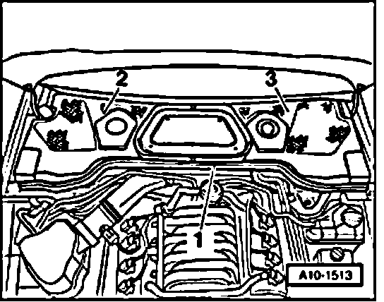
- Remove rubber seal -1- from plenum chamber cover.
- Remove plenum chamber covers -2- and -3-.
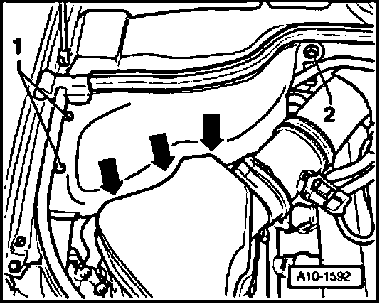
- Remove cover for right suspension strut dome; to do so, remove expanding clips -1- and bolt -2-.
NOTE: Note orientation of retaining clips -arrows- on installation.
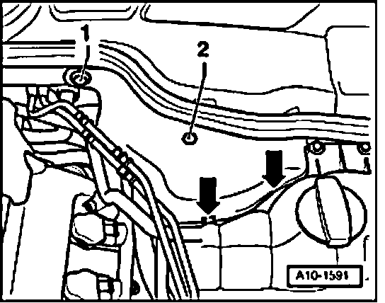
- Remove cover for left suspension strut dome; to do so, screw out bolt -2- and remove expanding clips -1-.
NOTE: Note orientation of retaining clips -arrows- on installation.
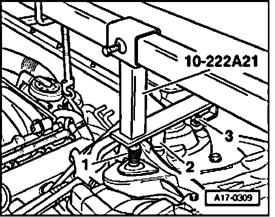
- Remove rear bolts -3- for dome brace.
- Attach support bar 10-222 A with supports 10-222 A21 to suspension strut domes.
- Supports are marked for left and right side of vehicle.
- Center resting point of supports is positioned on front bolts for dome brace.
- Supports 10-222 A21 are screwed on using rear bolts -3- for dome brace.
- Knurled screw -1- must be screwed down such that support plate rests on suspension strut dome.
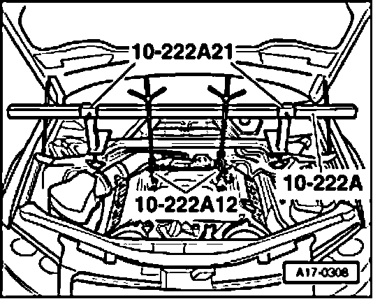
- Attach shackles 10-222 A12 to rear engine lifting eyes.
- Engage shackles 10-222 A12 at spindles of support bar 10-222 A.
- Pre-tension engine slightly with spindles of support bar.
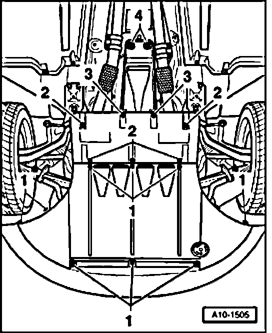
- Remove bolts/quick-release fasteners -1- and -2- and remove front noise insulation.
- Remove right front wheel.
- Remove right front wheel housing liner.
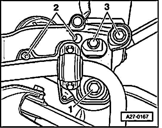
- Remove bolts -1 to 3- on both sides.
- Lower cross member.
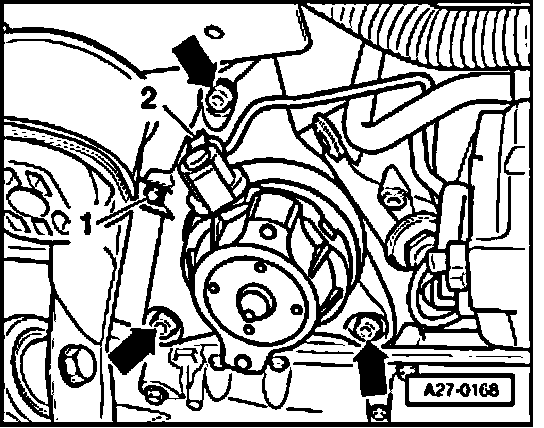
- Remove bolts -arrows-.
- Remove clamp -1-.
- Disconnect electrical connection -2- at engine mounting.
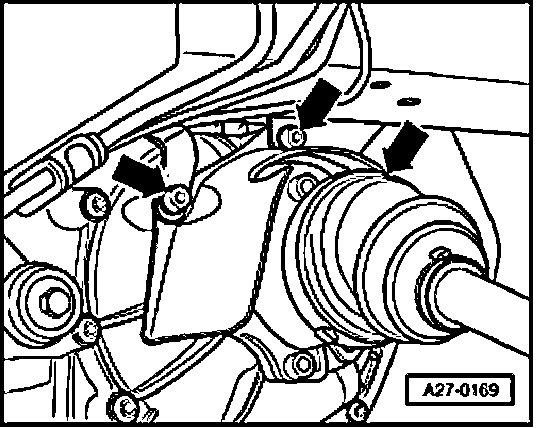
- Remove heat shield for right drive shaft -arrows-.
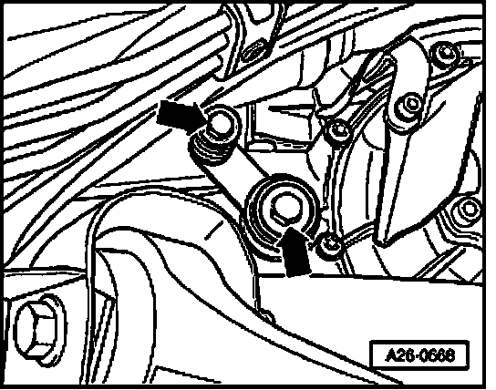
- Remove link plate for front exhaust pipe on right -arrows-.
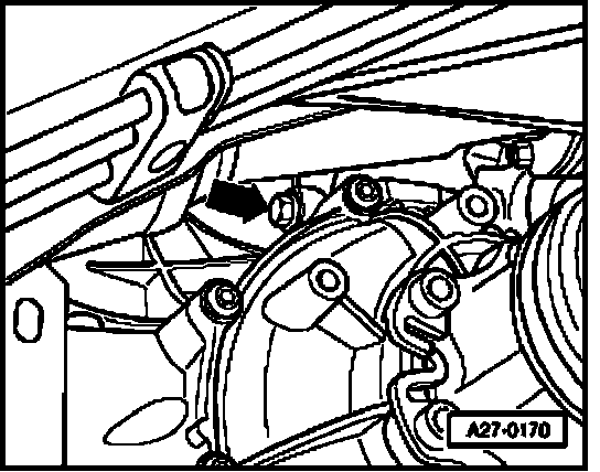
- Remove bolt -arrow-.
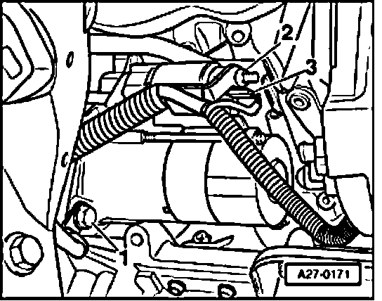
- Remove bolt -1-.
- Remove wire for terminal B+ -item 2-.
- Disconnect electrical connection for terminal 50 -item 3-.
- Take out starter downward.
Installing
Install in reverse order of removal, noting the following:
NOTE: Re-attach all cable ties at the same locations when re-installing.
- Install cross member.
- Reconnect battery.
- Deactivate "jacking" mode.
Tightening Torques
Component Nm
Starter to transmission
M10 45
M12 65
Terminal B+ to starter 16
Bracket for exhaust system 25
Heat shield to transmission 23
Engine support to cylinder block 40
Cable clamp to engine support 10
Engine mounting to cross member 23