Pump Unit, Removing and Installing
Refrigerant Circuit
Pump Unit, Removing and Installing
For complaint "poor heating performance", before removing pump-valve unit, check:
- The connection on the coolant circuit for correct installation of the supply and return line to the engine.
- The wiring to the pump for possible interchange ("+" and " -").
- The coolant circuit for thorough bleeding.
• Bleed the coolant circuit again. Follow the information provided. Refer to => [ Ventilation System Heat Output and Pump Valve Unit Function ] Ventilation System Heat Output and Pump Valve Unit Function.
• If Coolant Pump (V50) causes noise, check cooling system for complete bleeding air in coolant circuit may cause noise before removing pump-valve unit.
• Valves of pump valve unit are open when it is deenergized. If power supply or valve connection to front A/C control head Climatronic Control Module (J255) is interrupted, heat output of air conditioner cannot be regulated.
Removing
Special tools, testers and auxiliary items required
• Hose Clamps (3090 Bzw. 3094)
• Compressed air gun, commercially available
• Cooling System Tester (V.A.G 1274) and corresponding adapter
- Switch off ignition.
- Remove plenum chamber cover on right.
- Release pressure in cooling circuit by opening cap on coolant expansion tank.
- Mark the arrangement of coolant hoses - A - supply to pump valve unit and - B - return to engine.
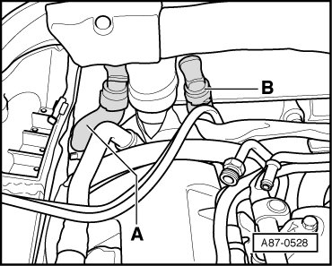
- Clamp two coolant hoses from engine to pump valve unit using Hose Clamps (V.A.G 3094).
- Remove coolant hoses - A - and - B - from connections.
- Connect one hose piece - A - and - B - to each of two connections.
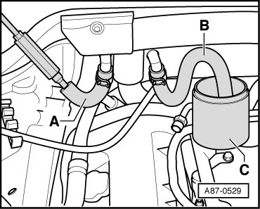
- Place container - C - beneath hose - B -.
- Using compressed-air gun, carefully blow coolant out of heater core and pump valve unit into container.
- Disconnect connectors - A - (to Right Heat Regulating Valve (N176)), - B - (to Left Heat Regulating Valve (N175)) and - C - (to Coolant Pump (V50)) from pump valve unit.
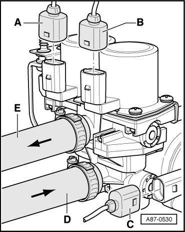
• The connectors are designed so as to prevent interchange:
- Mark arrangement of coolant hoses - D - supply to pump valve unit and - E - return to engine.
- Remove coolant hoses - D - and - E - from pump valve unit.
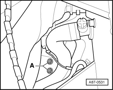
- Remove two hex nuts - A -.
- Mark coolant hoses to heater cores (- A -, supply to driver's heater core, - B -, return from front passenger's heater core, - C -, supply to front passenger's heater core and - D -, return from front passenger's heater core).
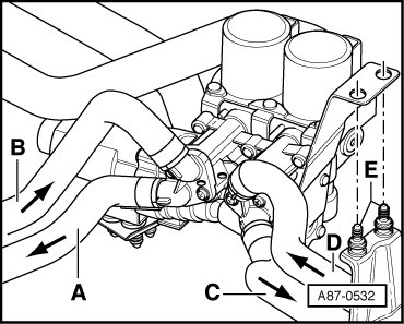
- Release pump-valve unit from rubber elements - E -.
- Remove coolant hoses from pump valve unit.
- Remove pump valve unit.
On left-hand drive vehicles, coolant hoses are connected to pump valve unit as follows:
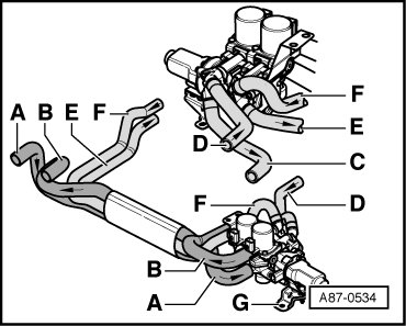
• Supply from engine to pump valve unit - A -
• Return from pump valve unit to engine - B -
• Supply to front passenger's heater core - C -
• Return from front passenger's heater core - D -
• Supply to driver's heater core - E -
• Return from driver's heater core - F -
• For removal, hex nuts at bracket - G - must also be removed on these vehicles.
Installing
Installation is carried out in the reverse order, when doing this note the following:
• Coolant Pump (V50) of pump-valve unit must only be operated after coolant circuit has been vented.
• Dry running of pump in pump valve unit leads to destruction.
- Connect 2-pin harness connector - C - to pump only after bleeding coolant circuit.
- After installation, check grommet between engine compartment and plenum chamber for proper seating.
- Check the DTC memory for the Climatronic Control Module (J255) A/C control head and erase any faults displayed if necessary => Vehicle diagnosis, testing and information system VAS 5051 in the "Guided Fault Finding" function.