Lock Carrier, Service Position
Service Position For Lock Carrier
Special tools, testers and auxiliary items required
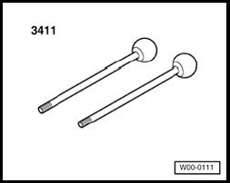
- 3411 Guide Rods
NOTE:
- For the service position, do not disconnect any refrigerant or coolant lines and no lines for power steering fluid circuit.
- Electrical harness connectors must not be disconnected.
- When installing lock carrier, make sure that no wires or hoses are pinched.
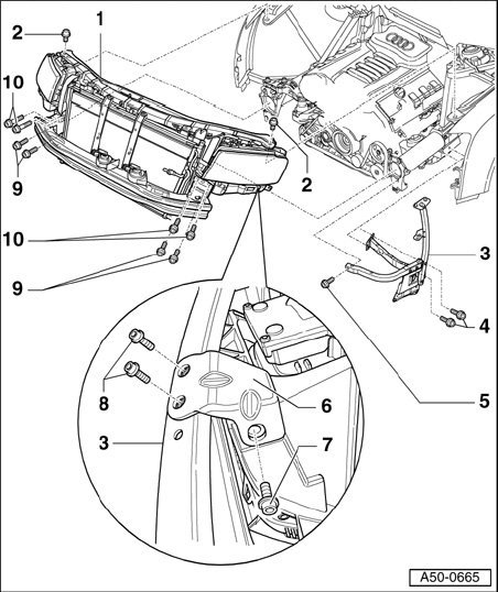
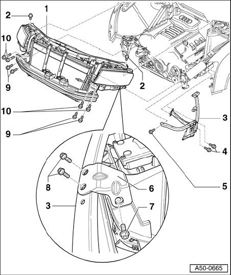
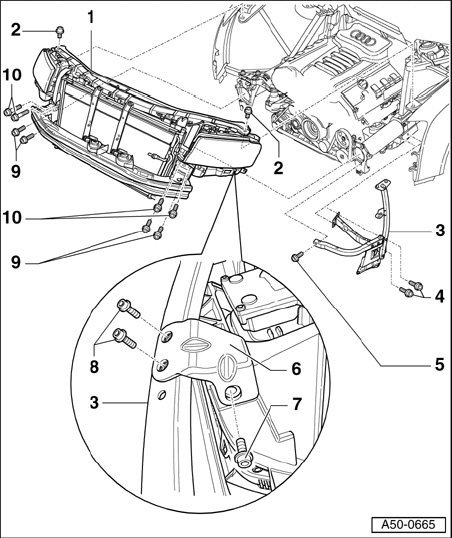
1 - Lock carrier
- For service position, front wheelhousing liner/front section removed.
- Bumper cover removed.
- Remove bolts - 2 - ; - 7 - ; - 9 - and - 10 -.
- Note the different lengths of bolts - 9 - and - 10 -.
- Guide Rods 3411 must be screwed respectively into threaded holes of both outer bolts - 10 -.
- Lock carrier can now be pulled approx. 10 cm toward front and secured in this position.
2 - Socket-head bolt
- M8x16
- 23 Nm
3 - Front brace
4 - Tone screw
- 25 Nm.
5 - Tone screw
- 25 Nm.
6 - Bracket for front brace
7 - Socket-head bolt
- 23 Nm.
8 - Combination bolt
- 10 Nm.
9 - Socket-head bolt
- M8x30 mm long
- 23 Nm.
10 - Socket-head bolt
- 23 Nm.
- M8x55 mm long
- For service position, only remove left bolt at top on left side and right bolt at top on right side.
- Screw in Guide Rods 3411 into free threaded holes.
- Remove bolts - 2 - ; - 7 - ; - 9 - and - 10 -.
- Bolt - 7 - is installed behind front wheelhousing liner/front section.
- Pull off lock carrier on Guide Rods 3411 toward front and secure.
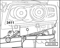
3411 special tool
- Screw special tool 3411 into threaded holes as shown.
- For service position, lock carrier can then be pulled toward approx. 10 cm on special tool and secured in this position.
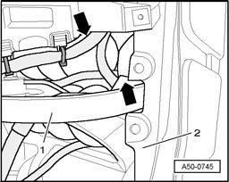
Installing lock carrier
- When installing, make sure that no wires or hoses - arrows - are pinched between lock carrier and brace - 1 - or fender - 2 -.