Ignition Coil: Testing and Inspection
Ignition Coils With Power Output Stages, Checking
Special Tools and Equipment
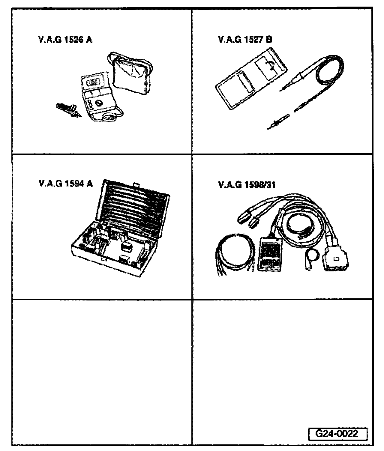
- VAG1526A
- VAG1527B
- VAG1594A
- VAG1598/31
Test sequence
NOTE: The ignition coil and power output stage are combined in one complete component.
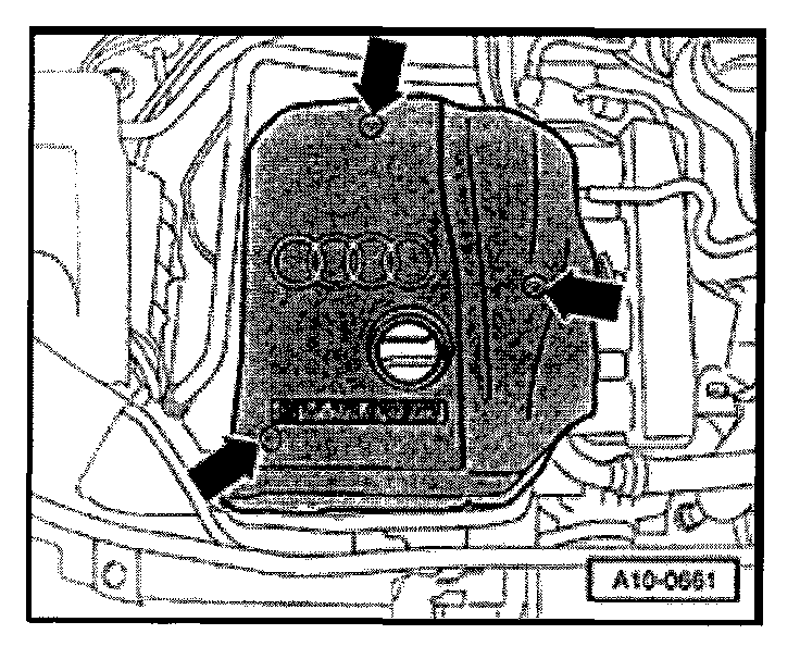
- Remove engine cover (arrows).
Recognize a non-functional or misfiring cylinder as follows:
- Check misfire recognition. Testing and Inspection
If misfires were recognized:
- Continue with test at indicated cylinder "If faulty cylinder is recognized".
If no misfires were recognized:
- Disconnect connectors from fuel injectors in sequence with engine running and observe engine operation.
or
- Compare spark plugs from all cylinders to each other. Check electrodes for carbon fouling.
If faulty cylinder is recognized:
- Switch spark plug from faulty cylinder with one from another cylinder.
If malfunction follows the spark plug:
- Replace spark plug.
If malfunction remains at original cylinder:
- Switch ignition coil from faulty cylinder with one from another cylinder.
If malfunction follows the ignition coil:
- Replace ignition coil.
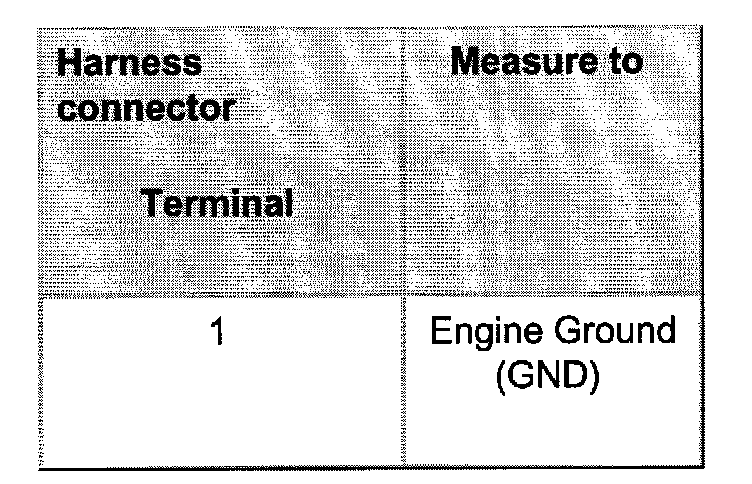
Check Ground (GND) connection
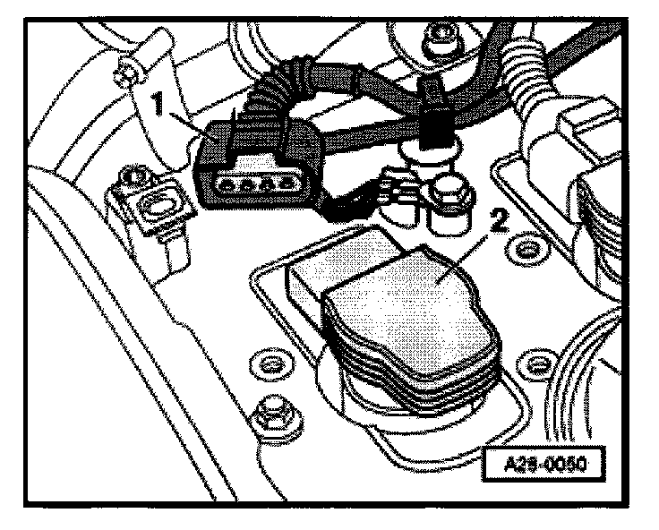
- Disconnect the 4-pin harness connector -1- at the ignition coil -2-.
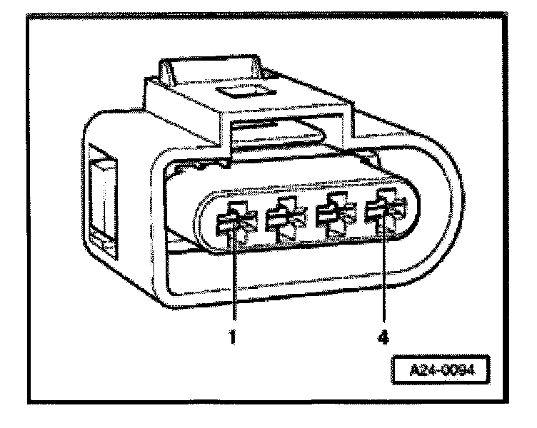
- Connect VAG1527B voltage tester as follows:
- LED must light up.
If LED does not light up:
- Check wire connections.
If LED lights up:
- Check voltage supply
Checking voltage supply
Test requirement:
- Fuses for engine electronics OK
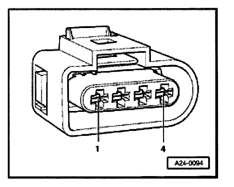
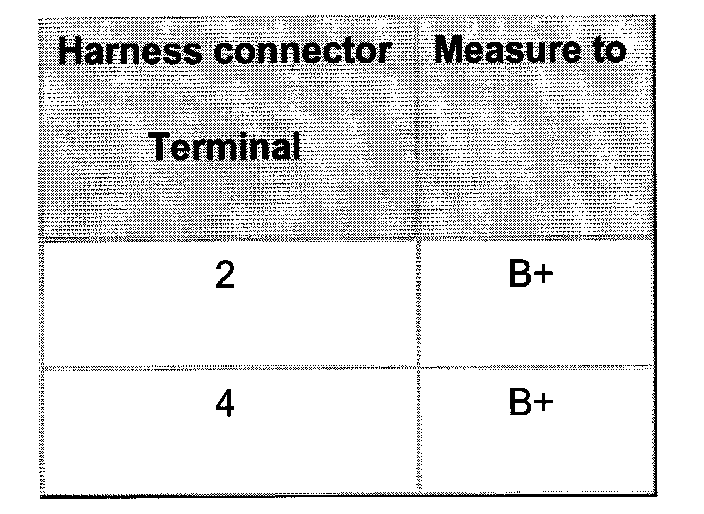
- Connect multimeter for voltage measurement as follows:
- Switch ignition on.
- Specification: approx. battery voltage
If specified value is obtained:
- Check activation of power output stages.
If specified value is not obtained;
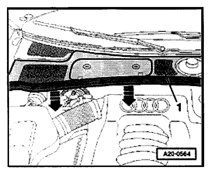
- Pull off rubber seal of plenum chamber cover in direction of arrow.
- Remove cover -1- toward front.
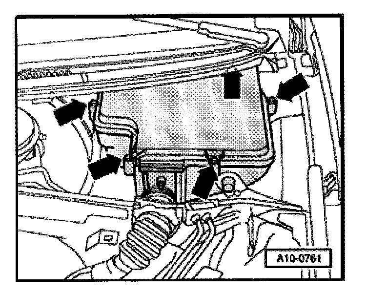
- Remove Heater Core E-box cover (arrows).
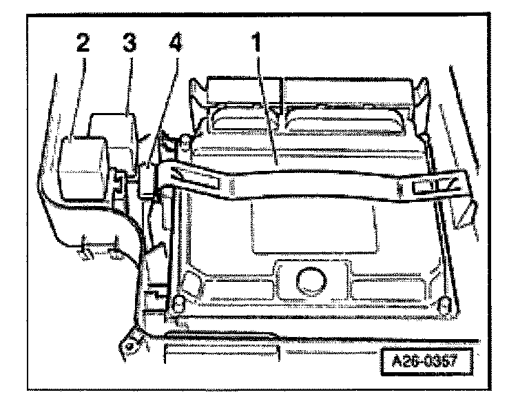
- Disconnect voltage supply relay -3-.
- Perform the following tests marked with dots:
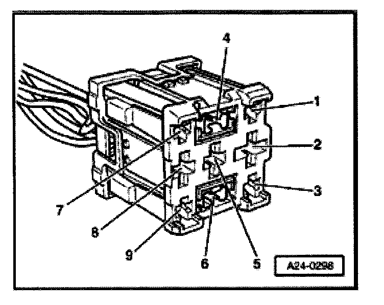
- Check wire connection from 3-socket relay carrier, position 2, terminal 6 to harness connector at ignition coil terminal 1.
- Check motronic Engine Control Module (ECM) voltage supply relay -J271-
Checking activation of power output stages
- Remove all harness connectors to injectors.
NOTE: Fuel must not be injected during the test to avoid damaging catalytic converter Connectors must therefore be disconnected from fuel injectors.
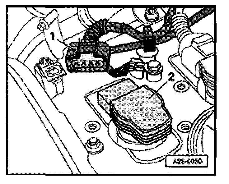
- Disconnect the 4-pin harness connector -1- at the ignition coil -2-.
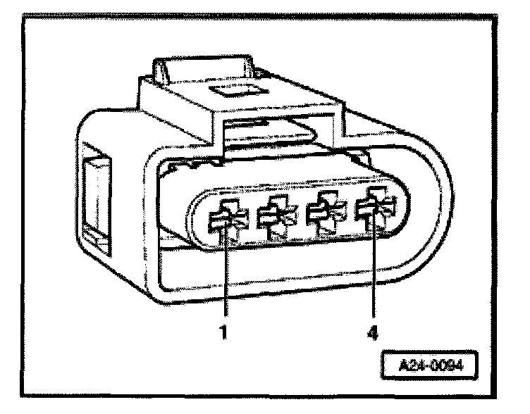
- Connect VAG1527B voltage tester to connector terminals 2 and 3.
- Operate starter briefly.
- LED must blink (brief blink signal).
If specified values are not obtained:
- Connect VAG1598/31 test box at wiring harness to Engine Control Module (ECM), do not connect ECM. Refer to "Scan Tool Testing/Wire and Component Testing Using VAG1598/31 Test Box" Testing and Inspection
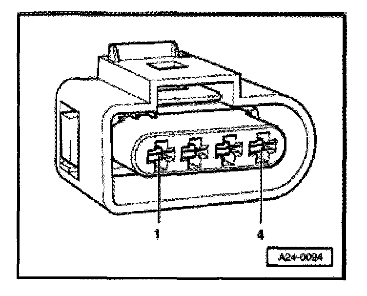
- Check the following wire connections for open circuit and short circuit to Ground (GND) and B+:
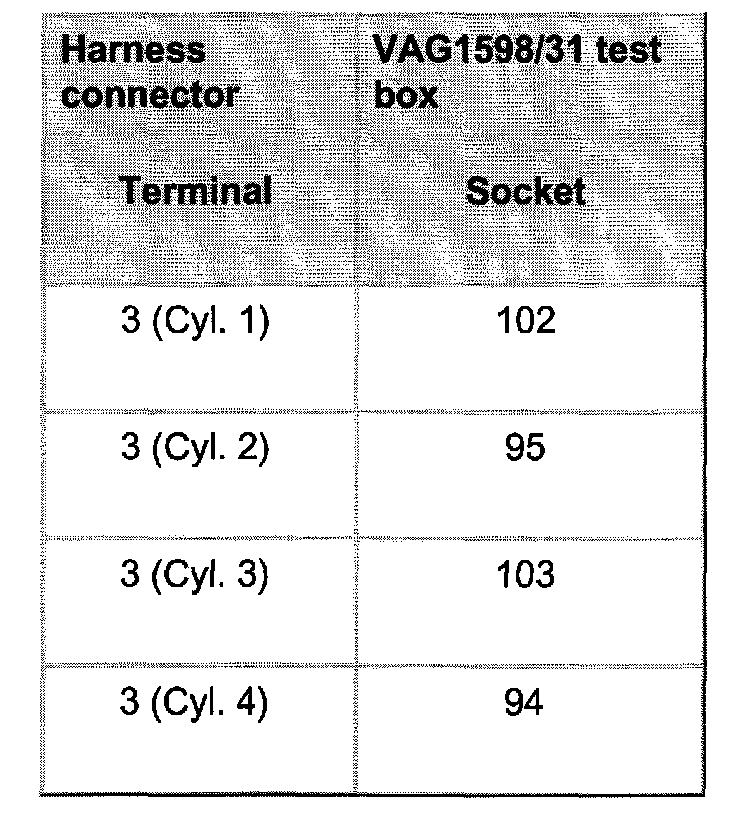
- Repair open circuit or short circuit if necessary.
If no malfunctions are found in wires:
- Replace the combined component, ignition coil with power output stage.