Catalytic Converter: Service and Repair
EXHAUST SYSTEM: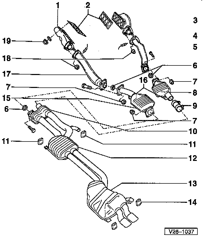
Legend:
1 Exhaust Manifold, Left
2 Exhaust Manifold Gaskets
3 Exhaust Manifold, Right
4 Heated Oxygen Sensors (HO2S)
- Bank 1
- Bank 2
5 Right Front Exhaust Pipe
6 Seal
7 Nut
8 Three Way Catalytic Converter (TWC), right
9 Double Clamp
10 Front Silencer
11 Retaining Loop
12 Center Silencer
13 Rear Silencer
14 Retaining Loop
15 TWC, Left
16 Hangers
17 Left Front Exhaust Pipe
18 Flange Connection Of Exhaust Manifold/Front Exhaust Pipe
19 Nut
Notes:
^ During removal and installation procedures, refer to the component location illustration above and component notes below.
^ Align exhaust system free of stress.
^ Seals and nuts should always be replaced.
^ Check exhaust system for leaks.
Component Notes:
Exhaust Manifold Gaskets (2):
- Metal side of gasket must face toward cylinder head.
Heated Oxygen Sensors (HO2S) Bank 1 and Bank 2 (4):
- Tighten to: 50 Nm (37 ft. lbs.).
- Lubricate threads G5, or equivalent, anti-seize grease.
- Do no allow G5 lubricant into slots of sensor.
Nut (7):
- Tighten to: 25 Nm (18 ft. lbs.).
Double Clamp (9):
- Tighten evenly.
- Always replaced when loosened.
- Tighten to: 40 Nm (30 ft. lbs.).
Retaining Loop (11):
- Bolts to fasten bracket to floor assembly.
- Tighten to: 25 Nm (18 ft. lbs.).
Retaining Loop (14):
- Bolts to fasten bracket to floor assembly.
- Tighten to: 25 Nm (18 ft. lbs.).
Flange Connection Of Exhaust Manifold/Front Exhaust Pipe (18):
- Tighten nuts evenly in several steps.
- Tighten to: 25 Nm (18 ft. lbs.).
Nut (19):
- Tighten to: 25 Nm (18 ft. lbs.).:
TWC HANGER COMPONENTS, RIGHT SIDE:
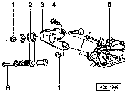
Legend:
1 Nut
2 Strap
3 Bracket
4 Bolt
5 Transaxle
6 Bolt
Note: During removal and installation procedures, refer to the component location illustration above and component notes below.
Component Notes
Nut (1)
- Tighten to: 25 Nm (18 ft. lbs.).
Bolt (4)
- Tighten to: 25 Nm (18 ft. lbs.).
Bolt (6)
- Tighten to: 25 Nm (18 ft. lbs.).
TWC HANGER COMPONENTS, LEFT SIDE:
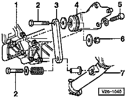
Legend
1 Transaxle
2 Bolt
3 Straps
4 Bracket
5 Bolt
6 Nut
7 Left Front Exhaust Pipe
Note: During removal and installation procedures, refer to the component location illustration above and component notes below.
Component Notes
Bolt (2)
- Tighten To: 25 Nm (18 ft. lbs.).
Bolt (5)
- Tighten To: 25 Nm (18 ft. lbs.).
Bolt (6)
- Tighten To: 25 Nm (18 ft. lbs.).
TWC TO FRONT EXHAUST PIPE:
Legend
1 Exhaust Manifold
2 Anti Twist Lock
3 Nuts
4 Heated Oxygen Sensors (HO2S)
5 Left Front Exhaust Pipe
Note:
^ During removal and installation procedures, refer to the component location illustration above and component notes below.
^ Left side shown, right side similar.
Component Notes
Nuts (3)
- Tighten evenly in several steps.
- Tighten to: 25 Nm (18 ft. lbs.).
HO2S (4)
- Tighten to: 50 Nm (37 ft. lbs.).
- Lubricate threads G5, or equivalent, anti-seize grease.
- Do no allow G5 lubricant into slots of sensor.