Lock Carrier, Service Position
Lock carrier, service position
NOTES: Do not remove noise insulation. Loosen only front quick-release screws, refer to Body and Frame - Sound Proofing/Insulation - Service and Repair - Procedures Service and Repair
Bumper removed
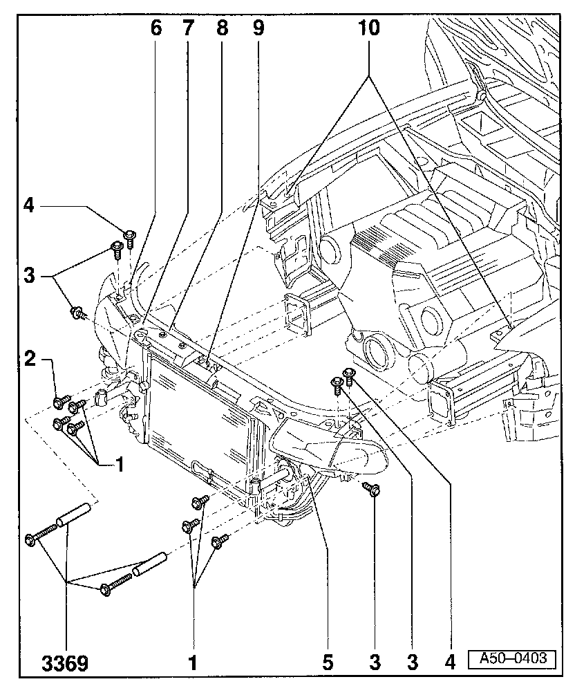
1. Combination bolt 45 Nm (33 ft lb)
2. Combination bolt 45 Nm (33 ft lb)
3. Combination bolt 10 Nm (7 ft lb)
4. Combination bolt 10 Nm (7 ft lb)
5. Access hold for special tool
For service position, attach special tool 3369 here
6. Cowl attachment hole
Attachment for service position
7. Lock carrier
For service position
- Screw special tool 3369 into threaded bore -5- on left side. See Fig. 1
- Remove left and right mounting screws -1-.
- Remove mounting bolts -3- and -4- and pull lock carrier -7- forward.
- Secure lock carrier. See Fig. 2.
8. Hood seal
9. Hood lock cable
10. Hole in side panel
NOTE: After assembly of the lock carrier, check headlight positioning and adjust if necessary
Fig. 1 Screw in special tool 3369
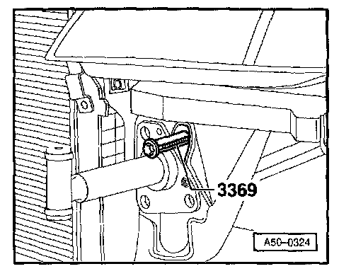
- Screw special tool 3369 in at left and right as shown.
- Pull lock carrier forward until rear hole in lock carrier aligns with front threaded hole in fender flange.
Fig. 2 Secure lock carrier
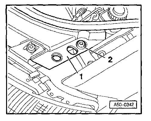
- Secure lock carrier with screws at left and right as shown.