Lower Timing Chain Cover
Lower Timing Chain Cover
Special tools, testers and auxiliary items required
• Counter Hold Tool (T10355)
• Thrust Piece (T10368)
• Torque Wrench (5-50 Nm) (V.A.G 1331)
• Torque Wrench (40-200 Nm) (V.A.G 1332)
• Engine Support Bridge (10-222 A)
• Engine Support Basic Set (T40091)
• Shackle (10-222 A/12)
• Bits (T10099)
• Silicone Sealing (D 174 003 A3)
• Flat Scraper
• Hand Drill with Plastic Brush Attachment
• Protective Eyewear
• Feeler Gauge
Removing
- Remove the noise insulation.
- Remove the right front wheel.
- Remove the right front wheel housing liner.
- Drain the engine oil. Refer to Maintenance Procedures.
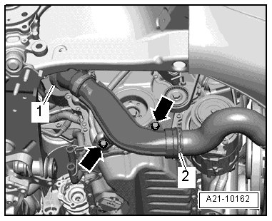
- Remove the bolts - arrows -.
- Remove the charge air pipe by lifting the clamps - 1 and 2 -.
- Remove the ribbed belt. Refer to => [ Ribbed Belt ] Ribbed Belt.
- Use the counter hold tool (T10355) to rotate the vibration damper to Top Dead Center - arrow -:
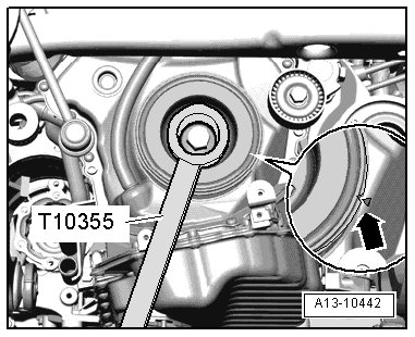
• The notch on the vibration damper must line up with the arrow mark on the lower timing chain cover.
The engine could be destroyed:
• In order NOT to change the valve timing, the crankshaft must NOT be moved out of the TDC position when the vibration damper bolt is removed.
- Use the counter hold tool (T10355) tool to remove the vibration damper bolt.
- Remove the vibration damper.
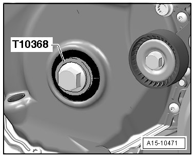
To avoid damaging the splines, only use the thrust piece (T10368) to install the vibration damper bolt.
- Install the vibration damper bolt and the thrust piece (T10368) again.
- Remove the plenum chamber cover.
- Remove the radiator grille.
- Install the engine support bridge (10-222 A) and support the engine in its installed position.
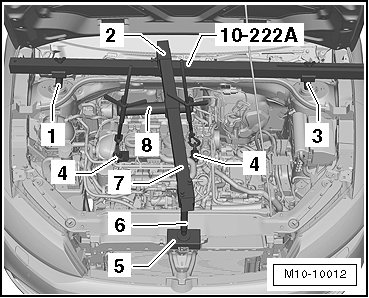
1. Support (10-222 A/31-2)
2. Bracket (T40091/3)
3. Support (10-222 A/31-1)
4. Shackle (10-222 A/12)
5. Base (10-222 A/31-4)
6. Support (10-222 A/31-3)
7. Cross bar (T40091/1)
8. Adapter (10-222 A/18)
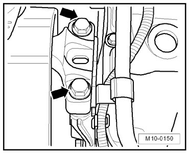
- Remove the engine mount to engine mount bracket bolts - arrows -.
- Remove the engine mount. Refer to => [ Engine and Transmission Mount Overview ] Removal and Replacement.
- Lift the engine approximately 50 mm and loosen the upper bolt for the engine mount bracket.
- Now, lower the engine approximately 100 mm.
- Free up electrical harness - arrow -.
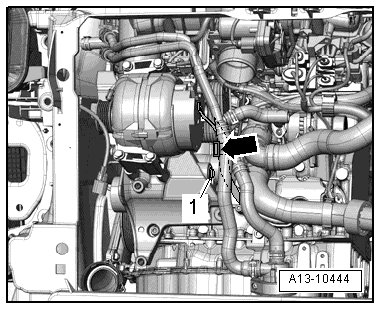
- Remove the bolt - 1 - and remove the ribbed belt tensioner from the accessory bracket.
- Remove the lower engine mount bracket bolts using the bits (T10099).
- Remove the engine mount bracket and the bolts.
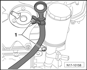
- Remove the bolts - 1 - and pull the oil dipstick guide tube out.
- Remove the wastegate bypass regulator valve (N75) bolts - arrows - from the turbocharger.
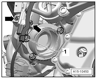
- Remove the turbocharger support bolts - 1 - and support.
- Remove the bolts - 1 through 15 -.
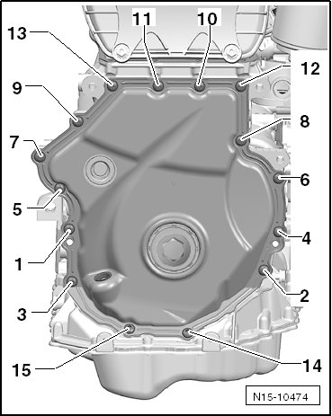
The lower timing chain cover could be damaged. To avoid deformation, do not hold between the bolting points.
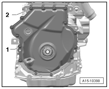
- Pry off the lower timing chain cover; when doing this, begin at - 1 and 2 -.
Installing
• Lower timing chain cover bolt tightening sequence and specification. Refer to => [ Lower Timing Chain Cover Bolt Tightening Sequence and Specification ] Timing Chain Covers Overview.
• Timing chain cover tightening specifications. Refer to => [ Timing Chain Covers Overview ] Timing Chain Covers Overview.
• Turbocharger tightening specifications. Refer to => [ Turbocharger Component Overviews ] Turbocharger Component Overviews.
• Ribbed belt tightening specification. Refer to => [ Ribbed Belt Overview ] Ribbed Belt Overview.
• Engine/transmission tightening specifications. Refer to => [ Engine and Transmission Mount Overview ] Removal and Replacement.
• Use silicone sealant (D 174 003 A3).
• The sealing surfaces must be completely free of oil and grease.
• Note the expiration date of the silicone sealant.
• The cover must be installed within 5 minutes after applying the silicone sealant.
• Replace the bolts which are being tightened to a torque angle.
• Replace sealing rings, seals and self-locking nuts.
- Remove any sealant residue on the cylinder block using a flat blade scraper.
Risk of eye injury.
• Wear protective eyewear.
- Seal off both sides of the seal with tape to prevent soiling.
- Remove any residual sealant on the cover with a rotating plastic brush.
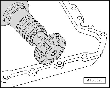
- Clean the sealing surfaces, they must be free of oil and grease.
- Install the cover with the old bolts and tighten:
• Tightening specification: 8 Nm.
- Check the gap between the cover and the housing using a feel gauge.
• It may not exceed 0.2 mm.
• If the gap exceeds 0.2 mm, replace the cover.
• It is not possible to measure between the cover the upper oil pan, however check the sealing surface for evenness.
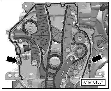
- Make sure both alignment bushings for centering the cover - arrows - are present.
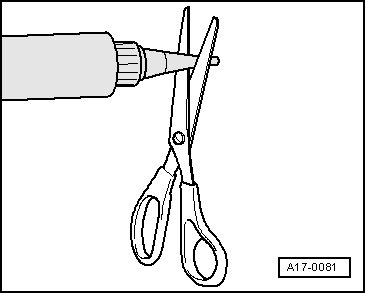
- Cut the sealant tube nozzle at the front mark (nozzle diameter: approximately 0.12 in).
- Apply the silicone sealant on the clean sealing surface of the cover as shown.
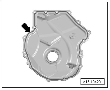
• Thickness of sealant bead: 2 to 3 mm.
• The cover must be installed within 5 minutes after applying the silicone sealant.
• The sealant bead may not be thicker than specified, otherwise excess sealant could enter the oil pan and clog the oil intake tube.
• Note the expiration date of the silicone sealant.
- Install the cover immediately and tighten the new bolts:
- Tighten the bolts - 1 through 15 - in 2 passes in the sequence shown:
1 - Tighten the bolts to 8 Nm
2 - Tighten the bolts an additional 45°(1/8) turn.
• After installing cover, allow the sealant to dry for approximately 30 minutes. Only after then may the engine oil be added.
- Fill the engine oil. Refer to Maintenance Procedures.
- Check the oil level. Refer to => [ Oil Level, Checking ] Testing and Inspection.
Further installation is in the reverse order of removal.