Ignition System: Service and Repair
Ignition System Component Overview
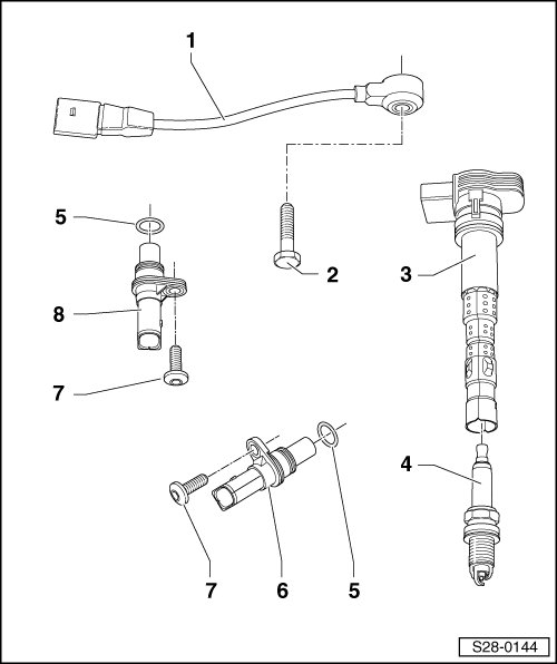
1 Knock Sensor 1 (G61)
• On the front of the cylinder head under the intake manifold.
• Contacts are gold plated.
• For the electrical connector, refer to => [ Connectors ].
• Removing and installing, refer to => [ Knock Sensor 1 (G61) ] Service and Repair.
2 Bolt
• 22 Nm
• The tightening specification influences the function of the knock sensor.
3 Ignition Coil with Power Output Stage
• Ignition coil 1 with power output stage (N70).
• Ignition coil 2 with power output stage (N127).
• Ignition coil 3 with power output stage (N291).
• Ignition coil 4 with power output stage (N292).
• Removing and installing, refer to => [ Ignition Coils with Power Output Stages ] Service and Repair.
4 Spark Plug
• 25 Nm
• If the spark plugs are replaced, grease the ignition coil with power output stage. Refer to => [ Installing ] Service and Repair.
• Note the change intervals, refer to the Maintenance Intervals.
• Type and electrode gap, refer to => [ Test Data and Spark Plugs ] Test Data and Spark Plugs.
• Remove and install using the spark plug removal tool (3122 B).
5 O-ring
• No replacement part available.
• Replace if damaged.
6 Engine Speed Sensor (G28)
• On the left front lower side of the cylinder block, next to the oil separator. Refer to => [ Engine Speed Sensor ].
• Removing and installing, refer to => [ Engine Speed Sensor (G28) ] Service and Repair.
7 Bolt
• 9 Nm
8 Camshaft Position Sensor (G40)
• Bolted to the front of the cylinder head cover. Refer to => [ Camshaft Position (CMP) Sensor ].
• For the electrical connector, refer to => [ Connectors ].
Camshaft Position (CMP) Sensor
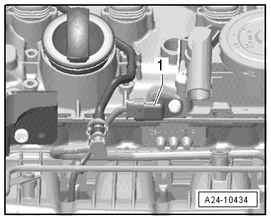
1. CMP sensor
Engine Speed Sensor
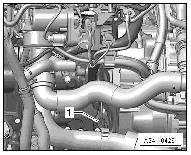
1. Engine Speed Sensor
Connectors
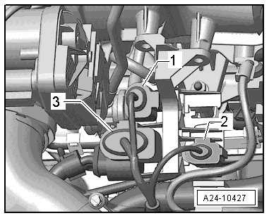
1. CMP sensor
2. Knock sensor 1
3. 8 pin connector for the fuel injectors