Intake Manifold
Intake Manifold
Special tools, testers and auxiliary items required
• Torque Wrench (5-50 Nm) (V.A.G 1331)
• Socket and Extended Bit (T10107 A)
Removing
• Follow all safety precautions. Refer to => [ Safety Precautions ] Multiport Fuel Injection.
• Pay attention to the rules of cleanliness. Refer to => [ Clean Working Conditions ] Multiport Fuel Injection.
- First, check whether a coded radio is installed. If so, obtain the anti-theft code.
- Disconnect the battery.
- Remove the engine cover with air filter. refer to => [ Engine Cover with Air Filter ] Engine Cover with Air Filter.
The fuel system is under pressure!
• Always wear protective eyewear and protective clothing to prevent injuries and fuel from coming in contact with your skin.
• Before loosening line connections, place a cloth around the connection point. Then release pressure by carefully pulling off the line.
- Disconnect the vacuum line - 2 - if present, the ventilation line - 1 - and the fuel supply line - 3 -.
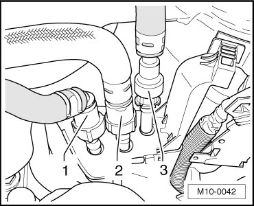
To release the lines - 1 and 2 -, press the circlip in.
Press the circlip upward into the housing to release the line - 3 -.
- Seal the lines so that the fuel system is not contaminated by dirt, etc.
- Disconnect the connectors - 1, 2 and 6 -.
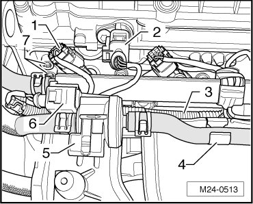
- Remove the wiring harness - 3 - from the transport strap.
- Pull the clamps - 4 - and retaining ring - 5 - out of the locking mechanism.
- Remove the bolts and remove transport strap.
- Remove the throttle valve control module (J338). Refer to => [ ] Service and Repair. The coolant hoses can remain attached, if present.
- Disconnect the connector - 1 - and hose for the crankcase ventilation - 3 -.
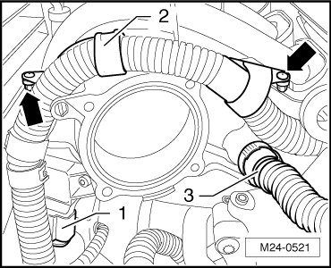
- Remove the wiring harness - 2 -. To do so, carefully press out the clips - arrows -.
- Pull the oil dipstick out - 1 - and press retaining ring - 4 - downward.
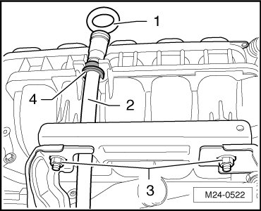
- Remove the noise insulation.
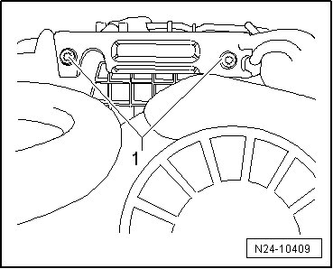
- Loosen the bolts or nuts - 1 - on the bottom side of the intake manifold.
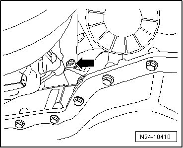
- Loosen the bolt - arrow - on the guide tube.
- Lay the guide pipe - arrows - aside.
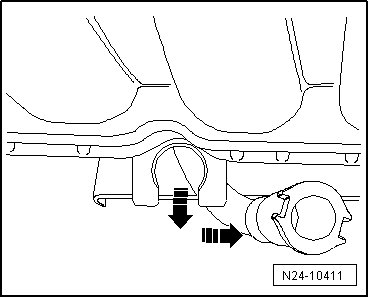
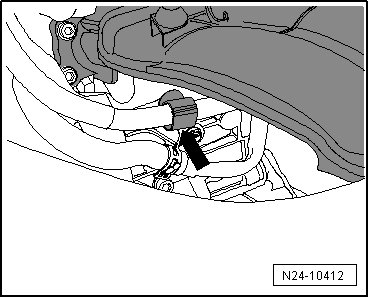
- Open the clip - arrow - on the leak detection pump (V144) vacuum hose.
- Remove the intake manifold bolts - arrows - from the cylinder head using the socket and extended bit (T10107 A).
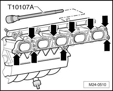
The bolts remain in the intake manifold.
- Remove the intake manifold upward at an angle.
Make sure that no bolts fall out.
- Seal the intake passages in the cylinder head using a clean cloth.
If the manifold is being replaced:
- Remove the fuel rail with injectors. Refer to => [ Fuel Injectors ] Fuel Injectors.
- Disconnect the vacuum hose for the leak detection pump.
- Remove the manifold absolute pressure sensor (G71).
Installing
Installation is performed in the reverse order of removal. When doing this note the following:
• Replace the seals between the intake manifold and cylinder head.
• Tighten the bolts for the intake manifold starting from the inside, working toward the outside in a diagonal sequence.
- Connect the battery.
- Bleed the fuel supply system. Refer to => [ Fuel System, Bleeding ] Fuel System, Bleeding.
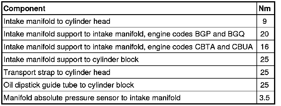
Tightening Specifications