Automatic Transmission/Transaxle: Locations
- Component Locations: Transmission Systems
Automatic transmission 09G
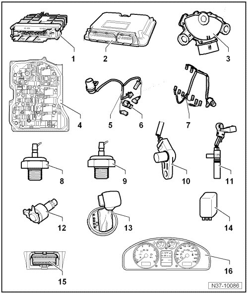
1 - Transmission Control Module (TCM) -J217-
• Located in front left wheel housing
2 - Engine Control Module (ECM)
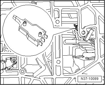
3 - Multi-Function Transmission Range (TR) Switch -F125- => [ Multi-Function Transmission Range (TR) Switch ] See Image Below.
4 - Valve body => [ Valve Body ] See Image Below.
• The valve body is bolted to underside of transmission housing and is covered by transmission oil pan
• The solenoid valves and pressure control valves are secured to the valve body
5 - Wiring harness, 8-pin => [ Transmission Fluid Temperature Sensor ] See Image Below.
• Wiring harness is attached to valve body in transmission
• With Transmission Fluid Temperature Sensor -G93-
6 - Transmission Fluid Temperature Sensor -G93- => [ Sensor Identification ] See Image Below.
7 - Wiring harness, 14-pin => [ Solenoid Valve Wiring Harness ] See Image Below.
• For solenoid valves
• Wiring harness is attached to valve body in transmission
8 - Automatic Transmission Hydraulic Pressure Sensor 1 -G193- => [ Sensor Identification ] See Image Below.
9 - Automatic Transmission Hydraulic Pressure Sensor 2 -G194- => [ Sensor Identification ] See Image Below.
10 - Transmission Input Speed (RPM) Sensor -G182- => [ Transmission Input Speed (RPM) Sensor and Transmission Output Speed (RPM) Sensor ] See Image Below.
• Sensor installed in transmission housing above valve body
11 - Transmission Output Speed (RPM) Sensor -G195- => [ Transmission Input Speed (RPM) Sensor and Transmission Output Speed (RPM) Sensor ] See Image Below.
• Sensor installed in transmission housing above valve body
12 - Shift Lock Solenoid -N110- => [ Selector Mechanism Assembly Overview ] See Image Below.
• Located in selector mechanism
13 - Tiptronic Switch -F189- => [ Tiptronic Switch ] See Image Below.
• Tiptronic switch is integrated into selector mechanism
14 - Power Supply Relay (terminal 50) -J682-
• Located in E box in engine compartment
15 - Data Link Connector (DLC)
16 - Transmission Range (TR) Display -Y6-
• Located in instrument cluster
Multi-Function Transmission Range
(TR) Switch
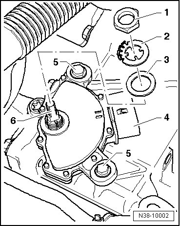
4 - Multi-Function Transmission Range (TR) Switch -F125-
Valve Body
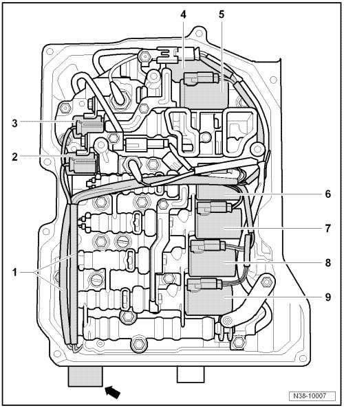
1 - Wiring harness for solenoid valves with 14-pin connector -arrow-
2 - Solenoid Valve 1 -N88-
3 - Solenoid Valve 2 -N89-
4 - Solenoid Valve 4 -N91-
5 - Solenoid Valve 6 -N93-
6 - Solenoid Valve 5 -N92-
7 - Solenoid Valve 9 -N282-
8 - Solenoid Valve 10 -N283-
9 - Solenoid Valve 3 -N90-
Transmission Fluid Temperature
Sensor
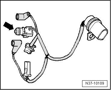
-arrow - Wiring harness - 8pin with integrated Transmission Fluid Temperature Sensor -G93-
Sensor Identification
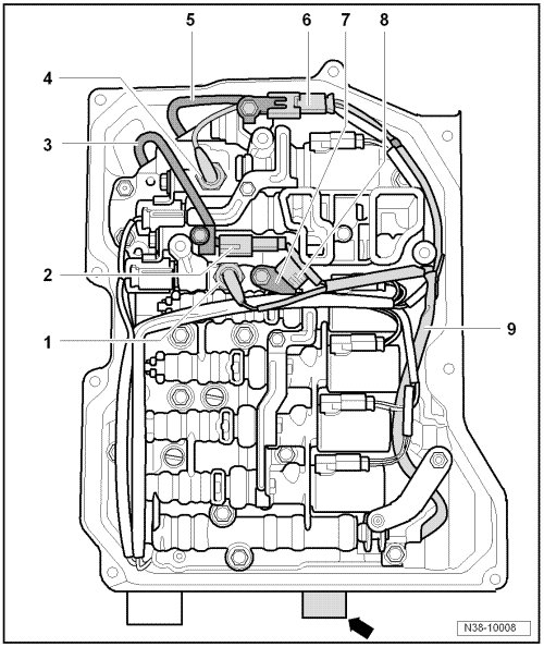
1 - Automatic Transmission Hydraulic Pressure Sensor 1 -G193-
Not installed in all transmissions
4 - Automatic Transmission Hydraulic Pressure Sensor 2 -G194-
Not installed in all transmissions
7 - Bracket for Transmission Fluid Temperature Sensor -G93-
8 - Transmission Fluid Temperature Sensor -G93-
9 - Wiring harness for sensor with 8-pin connector -arrow-
Transmission Input Speed (RPM)
Sensor and Transmission Output Speed (RPM) Sensor
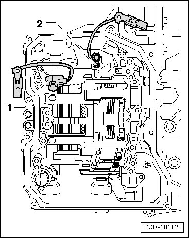
1 - Transmission Input Speed (RPM) Sensor -G182-
2 - Transmission Output Speed (RPM) Sensor -G195-
Solenoid Valve Wiring Harness
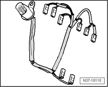
Solenoid Valve Wiring Harness -14pin
Selector Mechanism Assembly Overview
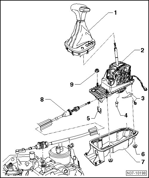
1 - Selector cover with knob
2 - Selector mechanism with selector lever
The following is located on the selector mechanism:
• Shift Lock Solenoid -N110-
The solenoid is permanently installed in the shift selector mechanism
and cannot be replaced separately. Removal and installation is only possible
in conjunction with selector mechanism
Tiptronic Switch
1 - Tiptronic Switch -F189-
Selector Lever Park Position Lock Switch -F319- is integrated with the tiptronic switch -F189-