EVAP System Assembly Overview
EVAP System Assembly Overview
CAUTION!
During all repair procedures on the fuel tank, be aware of the following:
• Make sure that the ground (-) strap between the fuel filler tube and body is securely fastened, to prevent electrostatic charging.
• Route lines of all types (for example, fuel, hydraulic, Evaporative Emission (EVAP), coolant, refrigerant, brake fluid and vacuum) and electrical wiring so that the original path is followed.
• To prevent damage to the lines, make sure there is sufficient clearance to all moving or hot components.
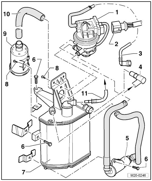
1 Leak Detection Pump (LDP) (V144)
• Under the wheel housing liner in the right rear wheel housing.
• On the Evaporative Emission (EVAP) canister.
• Pump is activated (pulsed) by the Engine Control Module (ECM).
• Removal and installation, refer to => [ EVAP Canister and Leak Detection Pump ] Service and Repair.
2 Connector
• 3 pin
3 Vacuum Line
• To disengage, press in the securing ring.
• Vehicles through MY 2009: from the intake manifold.
• Vehicles from MY 2010: from the connection to the vacuum line between the vacuum pump and the brake booster.
4 Vent Line
• Engine code BPS: from the switch over valve - item 7 - in => [ Switch Over Valve ] Removal and Replacement at fuel tank.
• Engine code BPR: from fuel tank see - item 10 - in => [ to EVAP Canister ] .
• To disengage, push securing ring forward.
5 Auxiliary Filter
6 Bolt, 11 Nm
7 EVAP Canister
• Under the wheel housing liner in the right rear wheel housing.
• Removal and installation, refer to => [ EVAP Canister and Leak Detection Pump ] Service and Repair.
8 Bolt, 3 Nm
9 LDP Air Filter
• Clean if contaminated.
10 Connecting Hose
• Intake side.
11 to EVAP Canister Purge Regulator Valve (N80)
• On the engine.