Fuel System Components
Fuel System Components
=> [ Fuel Tank ]
=> [ Fuel Level Sensor ]
Fuel Tank
Special tools, testers and auxiliary items required
• Torque Wrench (5 to 50 Nm) (V.A.G 1331)
• Engine/Transmission Jack (V.A.G 1383 A)
Removing
• Rear subframe must be lowered to remove the fuel tank.
- Read the safety precautions before beginning work. Refer to => [ Safety Precautions ] Fuel Supply.
- Observe the rules for cleanliness. Refer to => [ Clean Working Conditions ] Fuel Supply.
Empty the fuel tank as necessary using (VAS 5190). Refer to => [ Fuel Tank, Draining ] Fuel Tank, Draining.
- Remove the rear seat bench.
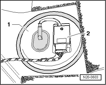
- Remove the cover - 1 - with fuel pump control module (J538) - 2 - from the fuel delivery unit.
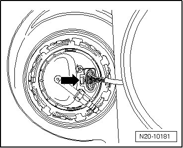
- Disconnect the 5 pin connector from the flange.
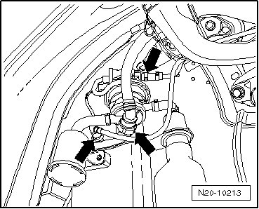
- Remove the right rear wheel.
- Remove the rear right wheel housing liner.
- Disconnect the vent lines and vacuum line - arrows - from the Evaporative Emission (EVAP) canister.
- Unclip the electrical wire - arrows - from the filler tube.
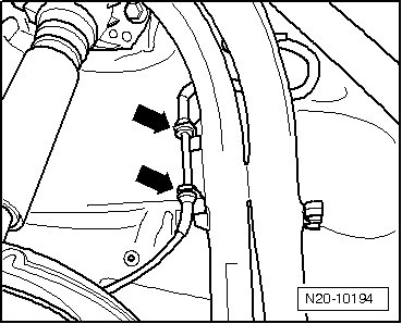
- Remove the fuel filler door unit.
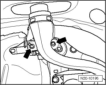
- Remove the fuel filler tube to body bolts - arrows -.
CAUTION!
The fuel supply line is under pressure! Wear protective goggles and protective clothing to prevent injuries and contact with skin. Before disconnecting the connection, wrap a cloth around the connection. Carefully disconnect the connection to release the pressure.
• Press in the securing ring to disengage the fuel lines.
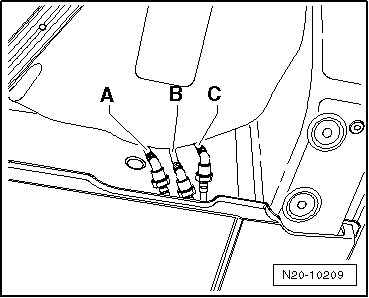
- Disconnect the white vent line - A -, green vacuum line - B - and black fuel line - C - at the connection point.
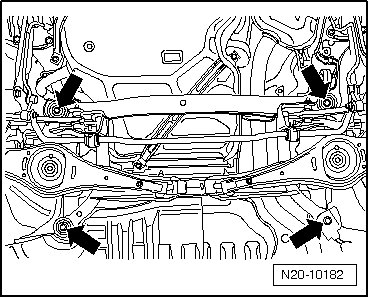
- Support the rear subframe using (V.A.G 1383 A).
- Loosen the bolts - arrows - and lower the rear subframe.
- Remove the securing strap bolts - arrows -. Support the fuel tank using (V.A.G 1383 A) beforehand.
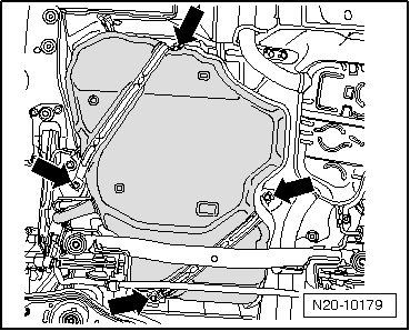
- Slowly lower the fuel tank.
• Fuel filler tube must be removed between the chassis and rear subframe. To do so, lift the fuel tank with help from a second technician, down from the (V.A.G 1383 A).
Installing
- With help from a second technician, guide the fuel filler neck between the rear subframe and chassis. Then place the fuel tank onto the (V.A.G 1383 A).
- Lift the fuel tank slowly up to the installed position and secure it and install the securing straps and bolts - arrows -.
• To secure the fuel tank straps, only bolts with loose washers may be used. If other bolts are used, the straps could twist when the bolts are tightened.
- Install the rear subframe to the chassis.
Further installation is performed in reverse order. When doing this note the following:
• Tightening specifications, refer to => [ Fuel Tank and Components Overview ] Fuel Tank and Components Overview.
• Make sure the vent and fuel lines are not kinked.
• Pull on the line connections to make sure they are securely connected.
• Check the Ground (GND) connection for the fuel tank/chassis at the filler tube.
• If the fuel delivery unit was replaced, adapt the Engine Control module (ECM) to the fuel pump, refer to "Guided Functions" in the vehicle diagnostic tester.
Fuel Level Sensor
Removing
- Remove the fuel delivery unit. Refer to => [ Fuel Delivery Unit ] Fuel Delivery Unit.
- Pull the fuel level sensor (G) slightly to the side and simultaneously upward.
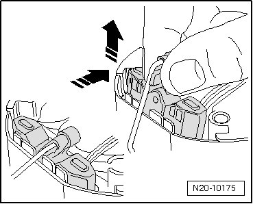
- If the sensor cannot be released this way, press the retaining tabs - arrows - to the side slightly.
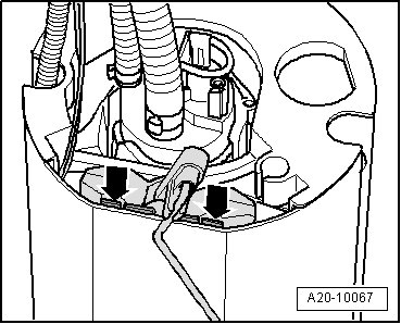
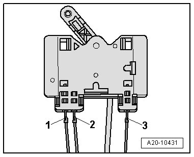
- Note the color of the wires for installing later.
- Disengage electrical connectors - 1 through 3 - and disconnect them. Bend the retaining hooks on the connector back.
Installing
- Connect the connectors - 1 through 3 -. Note the color coding.
- Pull on the connector to make sure it is securely connected.
- Insert the fuel level sensor in the guide on the fuel delivery unit and push down until it engages.
- Install the fuel delivery unit. Refer to => [ Fuel Delivery Unit ] Fuel Delivery Unit.