Camshaft Adjuster Valves
Camshaft Adjuster Valves
Special tools, testers and auxiliary items required
• Socket Wrench (T10072)
• TORX Bit Set (V.A.G 1766)
• Torque Wrench (5-60 Nm) (V.A.G 1783)
• Ratchet Insert 1/4" (VAS 6234)
• Sealant (D 176 501 A1)
• Sealing Compound (D 454 300 A2)
Removing
CAUTION!
When doing any repair work, especially in the engine compartment, pay attention to the following due to clearance issues:
• Route all lines and wires in their original locations.
• Make sure the wires have enough clearance to all moving or hot components.
- Remove the air guide cover - 1 -, disengage the clips sideways to do so.
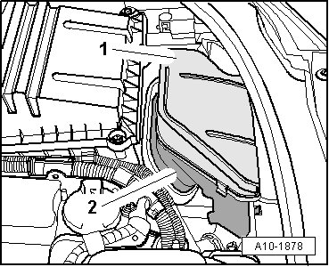
- Remove the air duct - 2 -.
- Remove the air filter housing and connecting hose, while doing this remove the bolt - A -, disconnect the connector - B - and remove the spring clip - C -. When reinstalling, observe the mark - D -.
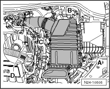
• Before disconnecting the connectors, mark them to the components.
- Disconnect the following connectors.
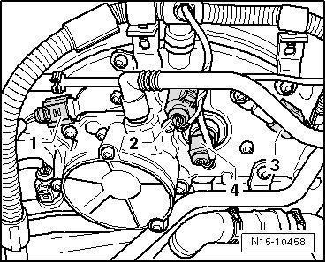
1 - Camshaft Position (CMP) Sensor (G40)
2 - Camshaft Adjustment Valve 1 (N205)
3 - CMP Sensor 2 (G163)
4 - Camshaft Adjustment Valve 1 (Exhaust) (N318)
- Free up the wiring harness.
- Remove the vacuum pump, if present. Refer to => [ Mechanical Vacuum Pump ] Mechanical Vacuum Pump.
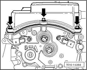
- Remove the 3 cylinder head cover bolts - arrows -.
- Remove the upper and lower coolant pipes from the timing chain cover.
- Remove the timing chain cover bolts - arrows - from the cylinder head.
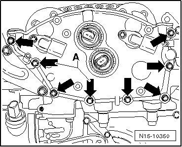
• Bolts - A - are not on vehicles with a mechanical vacuum pump.
CAUTION!
• Carefully cover the lower chain compartment so no parts can fall in.
• Do not completely remove the camshaft adjustment valve bolt so that the valve is not tilted when removed.
- Loosen the camshaft adjustment valve bolts - arrows - approximately 3 mm (5 turns) using (T10072).
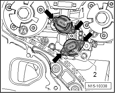
- Pull the camshaft adjustment valve out of control housing against the loosened bolts.
- Completely remove the bolts and remove the camshaft adjustment valve from the control housing.
Installing
CAUTION!
• The valve seat in the control housing must not be scored or scratched.
• The camshaft adjustment valves and control housing must be free of dust and contamination.
• The camshaft adjustment valves must not be subjected to knocks or impacts.
• Only remove the new camshaft adjustment valve from its packaging right before installation.
• Camshaft adjustment valves must not be pulled into valve the seat by the bolts. Only press them in by hand.
- Lubricate the seal with clean engine oil.
- Carefully install the camshaft adjustment valve into the housing and press it in perpendicular to the valve axis by hand until its seated.
- Tighten the bolts - arrows - to 3.8 Nm.
- 1 - camshaft adjustment valve 1.
- 2 - camshaft adjustment valve 1 (exhaust).
- Clean the sealing surfaces on the timing chain cover and on the cylinder head.
- If replacing the seals in the cover, refer to => [ Timing Chain Cover Seal, Installing ] Timing Chain Cover Seal, Installing.
- Make sure the seal - arrows - fits correctly inside the cylinder head cover.
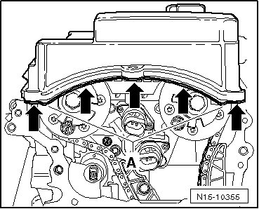
- If necessary, remove sealant residue in places - A -.
- Apply a thin bead of sealant (D 176 501 A1) to the sealing surfaces on the cylinder head cover.
- Apply some sealing compound (D 454 300 A2) to the places marked on cover - arrows -.
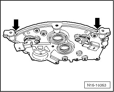
• The sealant (D 176 501 A1) hardens quickly.
- Slide the timing chain cover, at a slight angle, onto the camshaft adjustment valves. Ensure the cylinder head cover seal is not pressed back.
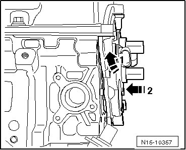
1 - Press the cover upward and under the cylinder head cover seal.
2 - Press the cover against the cylinder head and onto the alignment pins.
- Make sure the seal - arrows - fits correctly. It must not be pushed back.
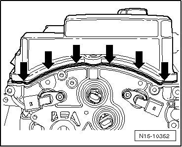
- Install all the bolts - arrows - and tighten them slightly.
• The bolts - A - are not on vehicles with a mechanical vacuum pump.
- Tighten all bolts to specifications, refer to - item 18 -=> [ Bolt ] Cylinder Head Overview.
- Tighten the 3 cylinder head cover bolts - arrows - to specifications, refer to - item 5 -=> [ Bolt ] Cylinder Head Overview.
- Install the vacuum pump, if present. Refer to => [ Mechanical Vacuum Pump ] Mechanical Vacuum Pump.
The rest of the installation is basically a reverse of the removal sequence.