Accelerator Pedal Module
Accelerator Pedal Module
Special tools, testers and auxiliary items required
• Release Tool (T10238)
Removing
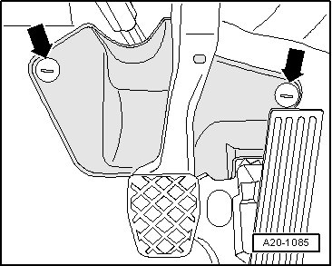
- Remove the steering column cover retainers - arrows - cover.
- Pry out the cap - 3 - using a screwdriver.
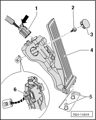
- Remove the bolt - 2 -.
- Disconnect the connector - 1 -. Refer to => [ Accelerator Pedal Module Connector, Disconnecting and Connecting ].
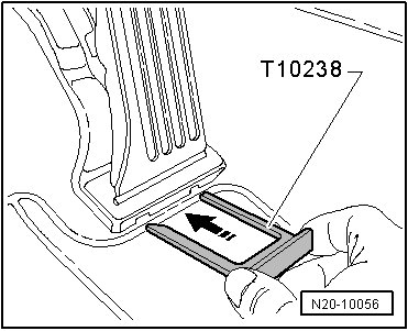
- Install the release tool (T10238) all the way into the opening as illustrated.
- Remove the accelerator pedal module.
Installing
- Connect the connector - 2 - to the accelerator pedal module - 5 -. Refer to => [ Accelerator Pedal Module Connector, Disconnecting and Connecting ].
- Push the accelerator pedal module onto the pins - 5 -.
- Insert the centering pin - 6 - into the hole in the floor panel.
- Secure the accelerator pedal module with the bolt - 2 -.
- Install the cap - 3 -.
- Install the steering column cover and retainers - arrows -.
- If the accelerator pedal module was replaced, adapt it to the Engine Control Module. Refer to "Guided Functions" in the vehicle diagnostic tester.
- If the accelerator pedal module was replaced in a vehicle with a automatic transmission, then the kick-down function must be programmed. Refer to "Guided Functions" in the vehicle diagnostic tester.
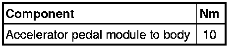
Tightening Specification
Accelerator Pedal Module Connector, Disconnecting and Connecting
• The accelerator pedal modules have connectors, which are disconnected and connected differently.
Disconnecting Connector 1K0 973 706
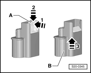
- Push the slider - A - (gray) in the - direction of arrow 1 - and then all the way down in the - direction of arrow 2 -.
- Hold the slider in this position and remove the connector housing - B - in the - direction of arrow 3 -.
The slider - A - stays in the lower position.
Connecting Connector 1K0 973 706
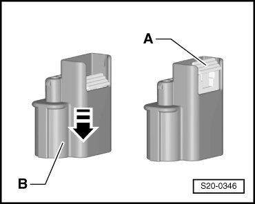
- Push the connector housing - B - in the - direction of the arrow - until the housing clicks into place.
The slider - A - automatically moves upward.
- Pull on the connector to make sure it is secure.
Disconnecting Connector 8K0 973 706
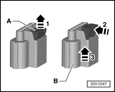
- Pull the slider - A - (red) all the upward in the - direction of arrow 1 -.
- Push the slider in the - direction of arrow 2 - and remove the connector housing - B - upward in the - direction of arrow 3 -.
The slider - A - stays in the upper position.
Connecting Connector 8K0 973 706
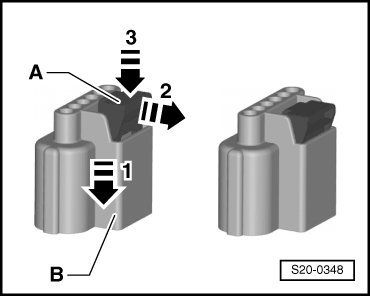
- Push the connector housing - B - all the way down in the - direction of arrow 1 -.
- Push the slider in the - direction of arrow 2 - and downward in the - direction of arrow 3 -.
The slider - A - can be pushed down only if the connector housing was pushed all the way down.
- Pull on the connector to make sure it is secure.