Engine Overview
Engine Overview
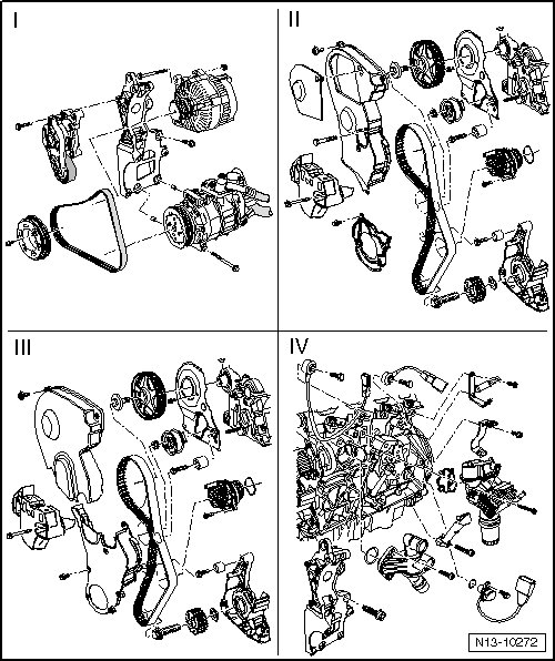
Part I => [ Ribbed Belt and Accessory Drive Overview ]
Part II => [ Toothed Belt Overview, Without Divided Toothed Belt Guard ]
Part III => [ Toothed Belt Overview, With Divided Toothed Belt Guard ]
Part IV => [ Cylinder Block and Components Overview ]
Ribbed Belt and Accessory Drive Overview
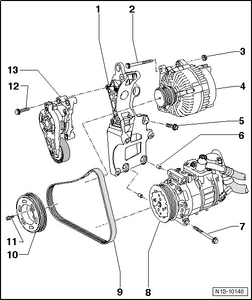
1 Accessory Bracket
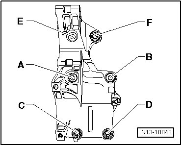
• Observe the bolt tightening sequence.
2 Bolt
• 23 Nm
3 Nut
• 23 Nm
4 Generator
• To facilitate installing the generator, slightly drive back the threaded bushings in the accessory bracket for the generator bolts.
5 Bolt
• 40 Nm
• Observe the tightening sequence.
6 Bushing
• Quantity: 2
7 Bolt
• 25 Nm
8 Air Conditioning (A/C) Compressor
9 Ribbed Belt
• Before removing, if reinstalling the old belt, mark the direction of rotation using chalk or a felt tip marker.
• Check for wear
• Do not kink
• Removing and installing, refer to => [ Ribbed Belt ] Ribbed Belt.
10 Vibration Damper Pulley
• For the ribbed belt.
11 Bolt
• 20 Nm + 90° (1/4) additional turn.
• Replace
12 Bolt
• 23 Nm
13 Belt Tensioner
• To release the tension on the ribbed belt, rotate using a open end wrench.
Accessory Bracket Bolt Tightening Sequence
Toothed Belt Overview, Without Divided Toothed Belt Guard
• Vehicles from 01.06 have a new toothed belt guard. Distinguishing feature: the upper toothed belt guard does not have a cover - item 25 - and the guard is divided in the engine mount bracket area. Vehicles with a divided toothed belt guard overview. Refer to => [ Toothed Belt Overview, With Divided Toothed Belt Guard ].
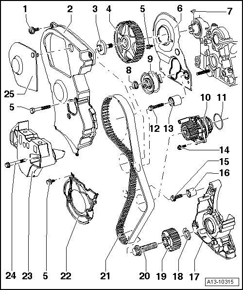
1 Bolt
• 10 Nm
2 Upper Toothed Belt Guard
3 Bolt
• 50 Nm + 180° (1/2) additional turn.
• Replace
• Use retainer (3036) to loosen and tighten.
4 Camshaft Sprocket
• Installed position is secured by a woodruff key.
5 Bolt
• 10 Nm
• Install using locking fluid.
6 Rear Toothed Belt Guard
7 Woodruff Key
• Check key for secure seating.
8 Nut
• 25 Nm
9 Semi Automatic Tensioning Roller
10 Coolant Pump
• Removing and installing, refer to => [ Coolant Pump ] Service and Repair.
11 O-ring
• Replace
12 Bolt
• 25 Nm
13 Idler Roller
14 Bolt
• 15 Nm
15 Bolt
• 35 Nm
16 Idler Roller
17 Sealing Flange
18 Diamond Disc
• Replace
19 Crankshaft Toothed Belt Gear
• There must be no oil on the contact surface between the toothed belt gear, diamond disc and crankshaft.
• Only possible to install in one position.
20 Bolt
• 90 Nm + 90° (1/4) additional turn.
• Replace
• Do not oil
• Use counter support (3415) to loosen and tighten.
21 Toothed Belt
• Before removing, if reinstalling the old belt, mark the direction of rotation using chalk or a felt tip marker.
• Check for wear
22 Lower Toothed Belt Guard
23 Engine Mount Bracket
24 Bolt
• 45 Nm
25 Toothed Belt Guard Cover
Toothed Belt Overview, With Divided Toothed Belt Guard
• Vehicles from 01.06 have a new toothed belt guard. Distinguishing feature: the upper toothed belt guard does not have a cover - item 25 - and the guard is divided in the engine mount bracket area. Vehicles without divided toothed belt guard overview. Refer to => [ Toothed Belt Overview, Without Divided Toothed Belt Guard ].
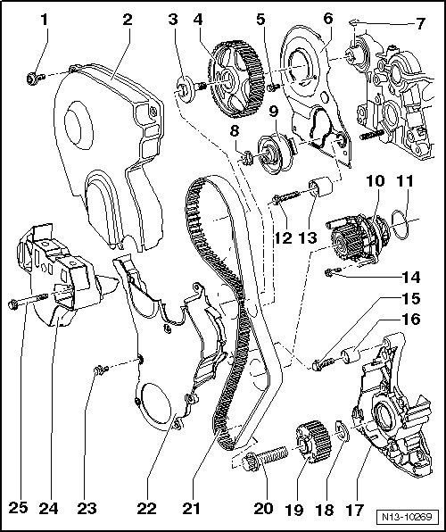
1 Bolt
• 10 Nm
2 Upper Toothed Belt Guard
3 Bolt
• 50 Nm + 180° (1/2) additional turn.
• Replace
• Use retainer (3036) to loosen and tighten.
4 Camshaft Sprocket
• Installed position is secured by a woodruff key.
5 Bolt
• 10 Nm
• install using locking fluid.
6 Rear Toothed Belt Guard
7 Woodruff Key
• Check the key for secure seating.
8 Nut
• 25 Nm
9 Semi Automatic Tensioning Roller
10 Coolant Pump
• Removing and installing, refer to => [ Coolant Pump ] Service and Repair.
11 O-ring
• Replace
12 Bolt
• 25 Nm
13 Idler Roller
14 Bolt
• 15 Nm
15 Bolt
• 35 Nm
16 Idler Roller
17 Sealing Flange
18 Diamond Disc
• Replace
19 Crankshaft Toothed Belt Gear
• There must be no oil on the contact surface between the toothed belt gear, diamond disc and crankshaft.
• Only possible to install in one position.
20 Bolt
• 90 Nm + 90° (1/4) additional turn.
• Replace
• Do not oil
• Use counter support (3415) to loosen and tighten.
21 Toothed Belt
• Before removing, if reinstalling the old belt, mark the direction of rotation using chalk or a felt tip marker.
• Check for wear
22 Lower Toothed Belt Guard
23 Bolt
• 8 Nm
• For the lower toothed belt guard.
• Quantity: 7
24 Engine Mount Bracket
25 Bolt
• 45 Nm
Cylinder Block and Components Overview
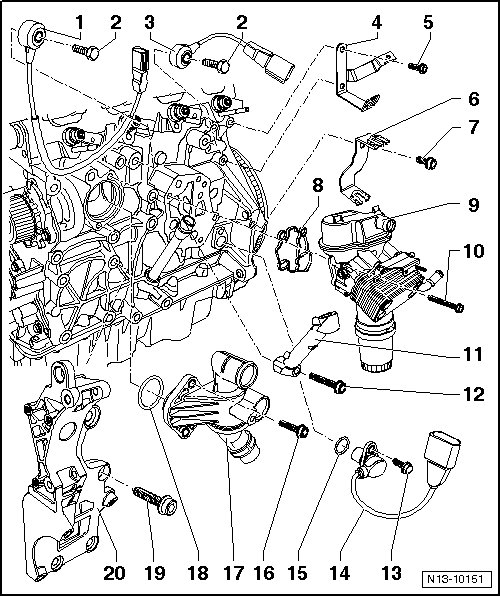
1 Knock Sensor (KS) 1 (G61)
• To remove, the coolant thermostat housing must be removed. Refer to => [ Coolant Thermostat Housing with Thermostat ] Coolant Thermostat Housing with Thermostat.
• Contacts are gold plated.
2 Bolt
• 20 Nm
• Tightening specification affects the function of the KS.
3 Knock Sensor (KS) 2 (G66)
• To remove, the oil filter bracket must be removed. Refer to => [ Oil Filter Bracket ] Oil Filter Bracket.
• Contacts are gold plated.
4 Wire Bracket
5 Bolt
6 Wire Bracket
7 Bolt
8 Gasket
• Replace
9 Oil Filter Bracket
• Overview, refer to => [ Oil Filter Bracket Overview ] Service and Repair.
10 Bolt
• 15 Nm + 90° (1/4) additional turn.
• Replace
11 Intake Manifold Support
12 Bolt
13 Bolt
• 10 Nm
14 Engine Speed (RPM) Sensor (G28)
15 Seal
• Replace
16 Bolt
• 15 Nm
17 Coolant Thermostat Housing with Thermostat
• Removing and installing, refer to => [ Coolant Thermostat Housing with Thermostat ] Coolant Thermostat Housing with Thermostat.
18 O-ring
• Replace
19 Bolt
• 40 Nm
20 Accessory Bracket
• Bolt tightening sequence.