System Description
HEATING / AIR CONDITIONING: AIR CONDITIONING SYSTEM: SYSTEM DESCRIPTION
1. GENERAL
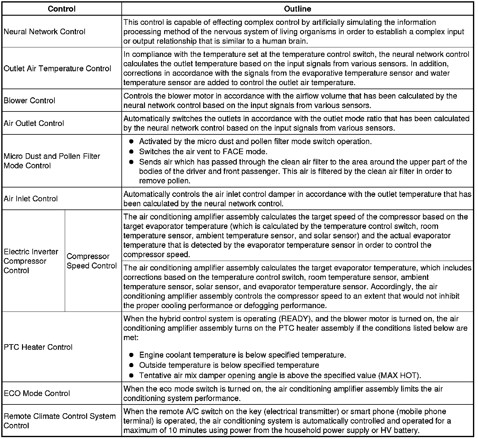
(a) The air conditioning system uses the following types of control.
2. NEURAL NETWORK CONTROL
* In previous automatic air conditioning systems, the air conditioning amplifier assembly determined the required outlet air temperature and blower air volume in accordance with the calculation formula that has been obtained based on information received from the sensors.
However, because the senses of a person are rather complex, a given temperature is sensed differently, depending on the environment in which the person is situated. For example, a given amount of sunlight can feel comfortably warm in a cold climate, or extremely uncomfortable in a hot climate. Therefore, as a technique for effecting a higher level of control, a neural network has been adopted in the automatic air conditioning system. With this technique, the data that has been collected under varying environmental conditions is stored in the air conditioning amplifier assembly. The air conditioning amplifier assembly can then effect control to provide enhanced air conditioning comfort.
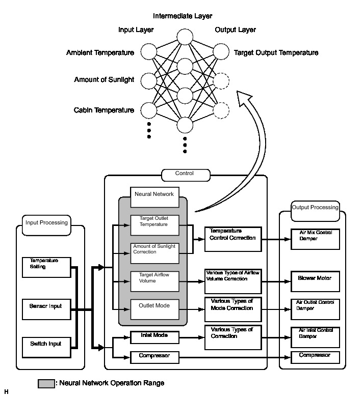
* The neural network control consists of neurons in the input layer, intermediate layer and output layer. The input layer neurons process the input data of the outside temperature, the amount of sunlight and the room temperature based on the outputs of the switches and sensors, and outputs it to the intermediate layer neurons. Based on this data, the intermediate layer neurons adjust the strength of the links among the neurons. The sum of these is then calculated by the output layer neurons in the form of the required outlet temperature, solar correction, target airflow volume and outlet mode control volume. Accordingly, the air conditioning amplifier assembly controls the servo motors and blower motor in accordance with the control volumes that have been calculated by the neural network control.
3. MODE POSITION AND DAMPER OPERATION
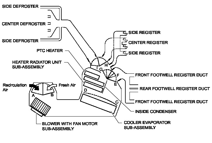
(a) Mode Position and Damper Operation
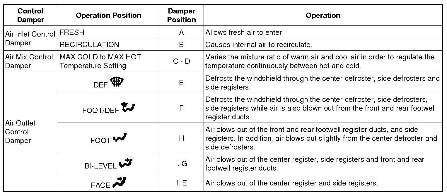
Functions of Main Dampers
4. AIR OUTLETS AND AIRFLOW VOLUME
(a) Air Outlets and Airflow Volume
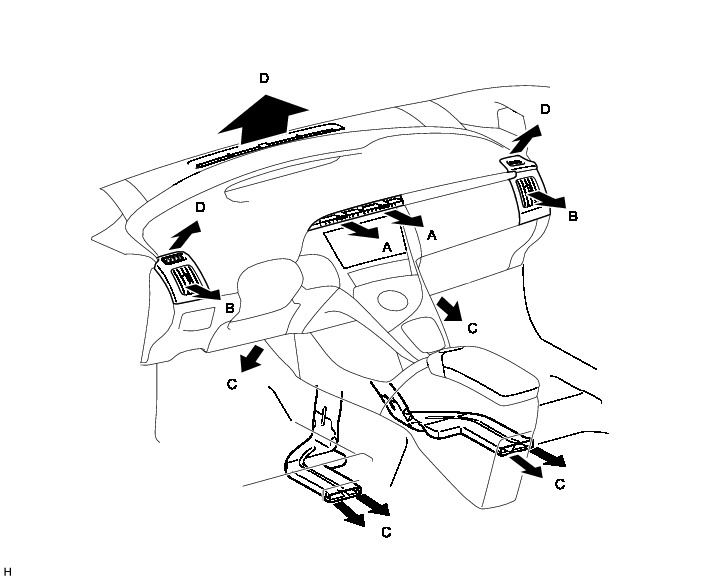
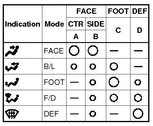
The size of each circle o indicates the ratio of airflow volume.
5. OUTLINE OF REMOTE CLIMATE CONTROL SYSTEM
(a) Outline
(1) When the remote A/C switch on the key (electrical transmitter) or smart phone (mobile phone terminal) is operated, the air conditioning system is automatically controlled and operated for a maximum of 10 minutes using power from the household power supply or HV battery.
HINT
* The remote climate control system operates regardless of the plug-in cable connection condition.
* When the plug-in cable is connected, the remote climate control system is operated using power from the HV battery or household power supply.
* When the plug-in cable is not connected, the remote climate control system is operated using power only from the HV battery.
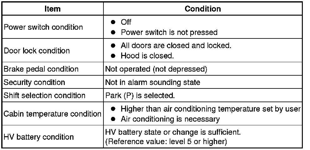
* The remote climate control system starts operating when all of the following operating conditions are met.
Operating Condition
(b) Function of Main Components
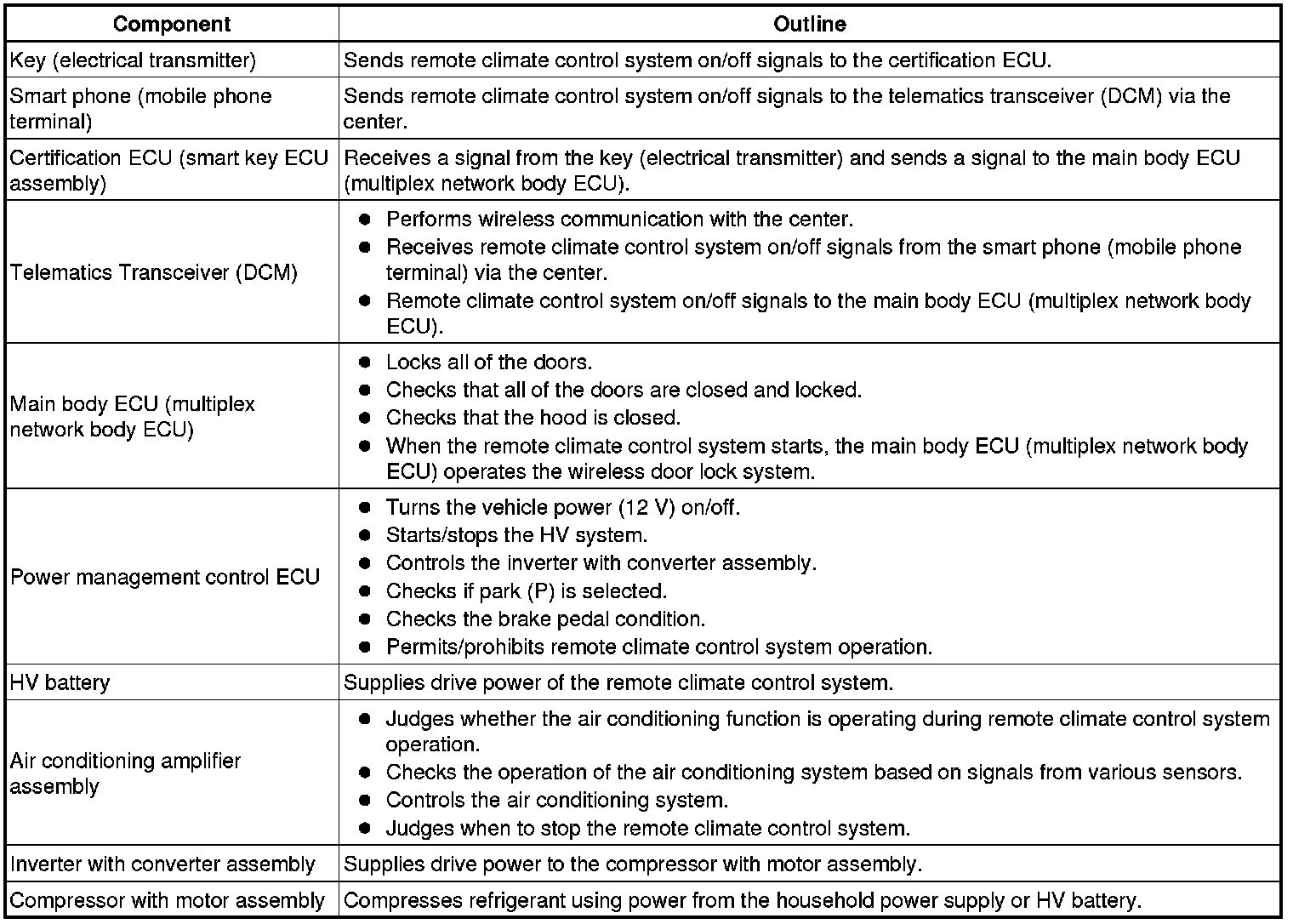
(1) Each component of the remote climate control system has the functions described in the table.
Function of Main Components
6. EJECTOR CYCLE SYSTEM
(a) In a conventional refrigerant cycle, liquid refrigerant gas is sent into the evaporator using the expansion valve, generating cold air. However, a rapid decrease in the refrigerant pressure forms swirls, causing energy loss. In an ejector cycle, the energy loss caused by the cooler expansion valve is utilized by the operation of the ejector that injects and expands a high-pressure refrigerant, thus improving energy consumption efficiency.
(b) The ejector includes nozzle, mixing and diffuser portions.
(c) A high temperature and pressure liquid refrigerant flowing from the condenser is introduced into the mixing section through the nozzle at high speeds as the nozzle is inwardly tapered. This decreases the refrigerant pressure in the vicinity of the nozzle, introducing low temperature and pressure gaseous refrigerant into the nozzle from the evaporator. Thus, both refrigerants are mixed in the mixing section and are introduced into the diffuser section.
(d) As the diffuser section is outwardly flared, the refrigerant flow rate in the diffuser decreases and the refrigerant pressure rises.
(e) Through these operations, the refrigerant pressure in the evaporator on the downwind side can be constantly kept lower than that on the upwind side, creating lower temperature conditions. Therefore, air cooled by the evaporator on the upwind side can be further cooled by that on the downwind side, thus improving the efficiency of the evaporator.
7. MICRO DUST AND POLLEN FILTER MODE CONTROL
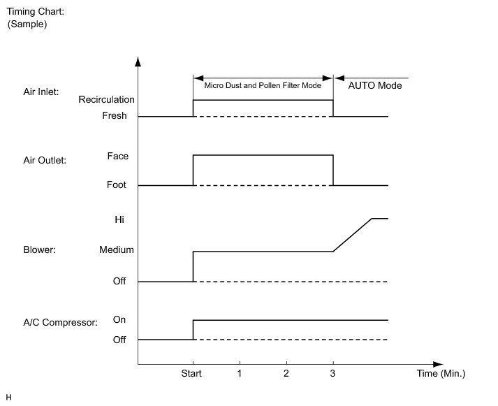
(a) When the micro dust and pollen filter mode switch is pressed, the micro dust and pollen filter mode control is activated.
(b) Then, the air vent is switched to FACE mode and recirculated pollen-free air flows in the area around the upper part of the bodies of the driver and front passenger.
(c) When the micro dust and pollen filter mode switch signal is input to the air conditioning amplifier assembly, the air conditioning amplifier assembly controls the compressor with motor assembly, air inlet control servo motor, air outlet control servo motor and blower motor as shown in the timing chart below.
(d) This control usually operates for approximately 3 minutes. However, when the outside temperature is low (5°C (41°F) maximum), it will operate for approximately 1 minute.
(e) After this control stops operating, the air conditioning amplifier assembly controls the air conditioning system using AUTO mode.
8. ECO MODE CONTROL
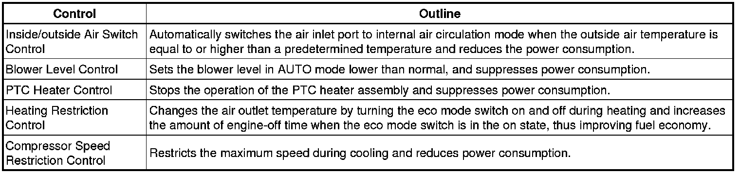
(a) Under the control of eco mode, the air conditioning amplifier assembly restricts the air conditioning system performance under specified conditions, thus improving fuel economy.
(b) Eco mode control is activated when the eco mode switch provided inside the integration control and panel sub-assembly is pressed, and then restricts the air conditioning system performance as described below.
9. COMPRESSOR WITH MOTOR ASSEMBLY
(a) Compressor Control
HINT
In order to ensure the proper insulation of the internal high-voltage portion of the compressor and the compressor housing, this vehicle has adopted ND-OIL 11 compressor oil with a high level of insulation performance. Therefore, never use compressor oil other than the ND-OIL 11 type compressor oil or its equivalent.
(1) The air conditioning amplifier assembly calculates the target compressor speed based on the target evaporator temperature (calculated from the temperature control switch, room temperature sensor, ambient temperature sensor, and solar sensor) and the actual evaporator temperature detected by the evaporator temperature sensor. Then, the air conditioning amplifier assembly transmits the target speed to the power management control ECU. The power management control ECU controls the A/C inverter based on the target speed data in order to control the compressor with motor assembly to a speed that suits the operating condition of the air conditioning system.
(2) The air conditioning amplifier assembly calculates the target evaporator temperature, which includes corrections based on the temperature control switch, room temperature sensor, ambient temperature sensor, automatic light control sensor, and evaporator temperature sensor. Accordingly, the air conditioning amplifier assembly controls the compressor speed to an extent that does not inhibit proper cooling performance or defogging performance.
(3) The compressor with motor assembly uses high-voltage alternating current. If a short or open circuit occurs in the compressor with motor assembly wiring harness, the power management control ECU will cut off the A/C inverter circuit in order to stop the power supply to the compressor motor.
10. PTC HEATER
(a) General
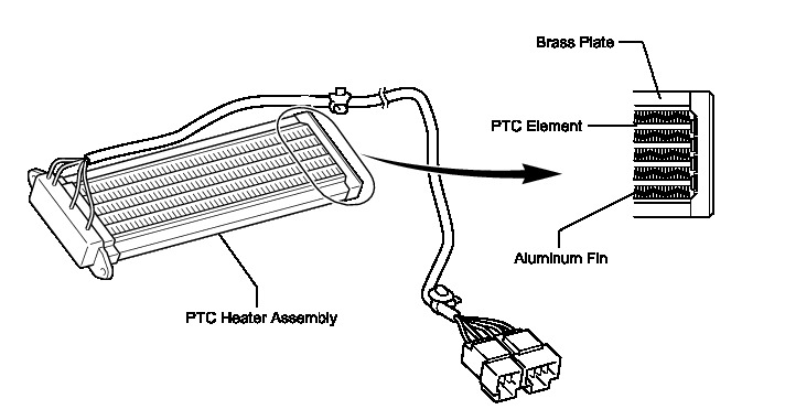
(1) The quick heater assembly is located above the heater core in the air conditioning unit.
(2) The quick heater assembly consists of a PTC element, aluminum fins, and brass plates. When current is applied to the PTC element, it generates heat to warm the air that passes through the unit.
(b) Quick heater assembly operating conditions
The quick heater assembly is turned on and off by the air conditioning amplifier assembly in accordance with the engine coolant temperature, ambient temperature, engine speed, temperature setting, and electrical load (generator power ratio).
11. BLOWER MOTOR
The blower motor with fan sub-assembly has a built-in blower controller, and is controlled using duty control performed by the air conditioning amplifier assembly.
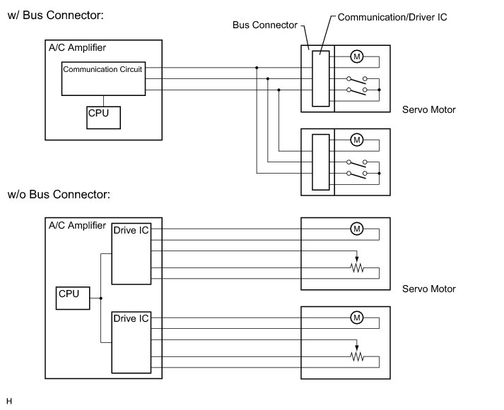
12. BUS CONNECTOR (AIR CONDITIONING HARNESS ASSEMBLY)
(a) A bus connector is used in the wire harness connection that connects the servo motors to the air conditioning amplifier assembly.
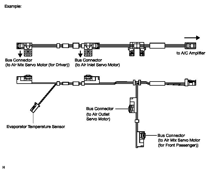
(b) Each bus connector has a built-in communication/driver IC which communicates with the air conditioning amplifier assembly, actuates the servo motor, and has a position detection function. This enables bus communication for the servo motor wire harness, for a more lightweight construction and a reduced number of wires.
13. SERVO MOTOR
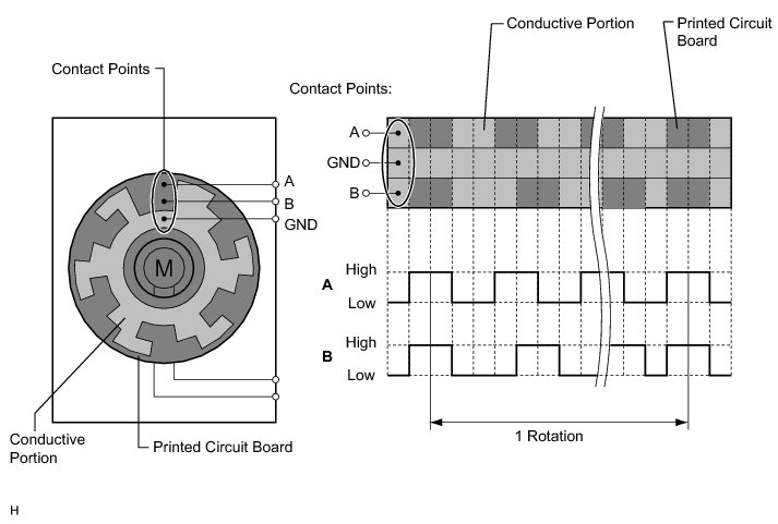
The pulse pattern type servo motor consists of a printed circuit board and a servo motor. The printed circuit board has three contact points, and can transmit two ON-OFF signals to the air conditioning amplifier assembly based on the difference of the pulse phases. The bus connector can detect the damper position and movement direction with these signals.
14. EVAPORATOR TEMPERATURE SENSOR
The evaporator temperature sensor detects the temperature of the cool air immediately through the evaporator in the form of resistance changes, and outputs it to the air conditioning amplifier assembly.
15. ROOM TEMPERATURE SENSOR
The room temperature sensor detects the cabin temperature based on changes in the resistance of its built-in thermistor and sends a signal to the air conditioning amplifier assembly.
16. AMBIENT TEMPERATURE SENSOR
The ambient temperature sensor detects the outside temperature based on changes in the resistance of its built-in thermistor and sends a signal to the air conditioning amplifier assembly.
17. SOLAR SENSOR (AUTOMATIC LIGHT CONTROL SENSOR)
The solar sensor (automatic light control sensor) detects changes in the amount of sunlight and outputs it to the air conditioning amplifier assembly in the form of voltage changes.
18. AIR CONDITIONING PRESSURE SENSOR
The air conditioning pressure sensor detects the refrigerant pressure and outputs it to the air conditioning amplifier assembly in the form of voltage changes.