Installation
2AZ-FE ENGINE MECHANICAL: ENGINE ASSEMBLY:
INSTALLATION
1. INSTALL ENGINE COOLANT TEMPERATURE SENSOR
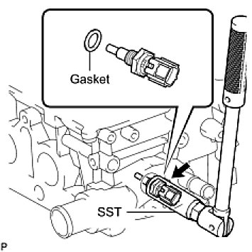
(a) Using SST, install a new gasket and the ECT sensor.
SST: 09817-33190
Torque: 20 Nm (208 kgf-cm, 15 ft-lbf)
2. INSTALL ENGINE OIL PRESSURE SWITCH ASSEMBLY
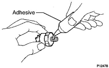
(a) Clean the threads of the oil pressure switch. Apply adhesive to 2 or 3 threads of the oil.
Adhesive:
Part No. 08833-00080 THREE BOND 1344 or equivalent
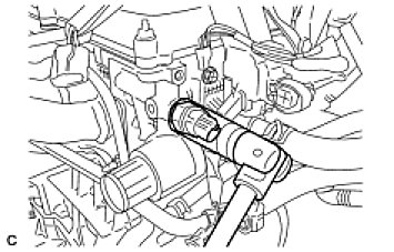
(b) Using a 24 mm deep socket wrench, install the oil pressure switch.
Torque: 15 Nm (153 kgf-cm, 11 ft-lbf)
3. INSTALL RADIO SETTING CONDENSER
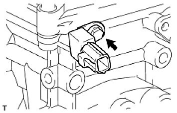
(a) Install the condenser with the bolt.
Torque: 10 Nm (102 kgf-cm, 7 ft-lbf)
4. INSTALL KNOCK SENSOR
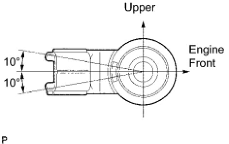
(a) Install the sensor with the nut as shown in the illustration.
Torque: 20 Nm (204 kgf-cm, 15 ft-lbf)
5. INSTALL CAMSHAFT TIMING OIL CONTROL VALVE ASSEMBLY (Installation)
6. INSTALL IGNITION COIL ASSEMBLY
(a) Install the 4 ignition coils with the 4 bolts.
Torque: 9.0 Nm (92 kgf-cm, 80 in-lbf)
7. INSTALL ENGINE MOUNTING BRACKET RH
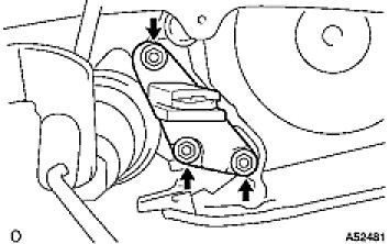
(a) Remove the engine mounting bracket RH with the 3 bolts.
Torque: 54 Nm (551 kgf-cm, 40 ft-lbf)
8. INSTALL OIL COOLER PIPE (w/ Oil Cooler)
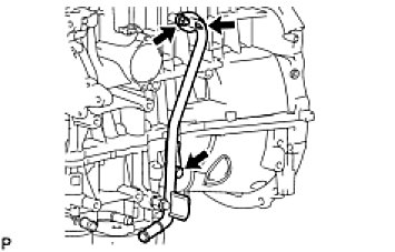
(a) Install a new gasket and the pipe with the bolt and 2 nuts.
Torque: 9.0 Nm (92 kgf-cm, 80 in-lbf)
9. INSTALL NO. 1 WATER BY-PASS PIPE
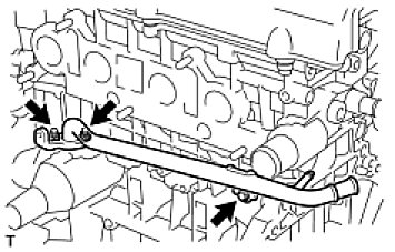
(a) Install a new gasket and the pipe with the bolt and 2 nuts.
Torque: 9.0 Nm (92 kgf-cm, 80 in-lbf)
10. INSTALL THERMOSTAT (Installation)
11. INSTALL WATER INLET (Installation)
12. INSTALL EXHAUST MANIFOLD CONVERTER SUB-ASSEMBLY
(a) Except for PZEV:
(1) Install a new gasket onto the cylinder head.
(2) Temporarily tighten the exhaust manifold converter with the 5 nuts.
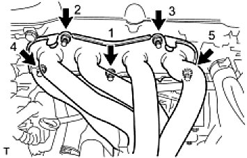
(3) Tighten the 5 nuts in the sequence shown in the illustration.
Torque: 37 Nm (378 kgf-cm, 27 ft-lbf)
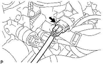
(4) Connect the air-fuel ratio sensor connector.
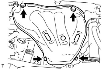
(5) Install the exhaust manifold heat insulator with the 4 bolts.
Torque: 12 Nm (122 kgf-cm, 9 ft-lbf)
(b) For PZEV:
(1) Install a new gasket onto the cylinder head.
(2) Temporarily tighten the exhaust manifold converter with the 5 nuts.
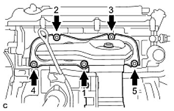
(3) Tighten the 5 nuts in the sequence shown in the illustration.
Torque: 37 Nm (378 kgf-cm, 27 ft-lbf)
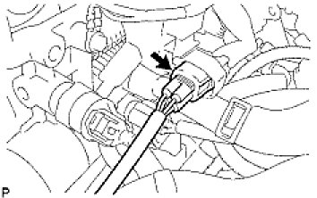
(4) Connect the air-fuel ratio sensor connector.
13. INSTALL NO. 2 MANIFOLD STAY
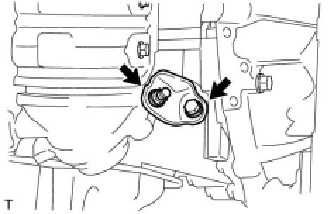
(a) Install the stay with the bolt and nut.
Torque: 44 Nm (449 kgf-cm, 32 ft-lbf)
14. INSTALL MANIFOLD STAY
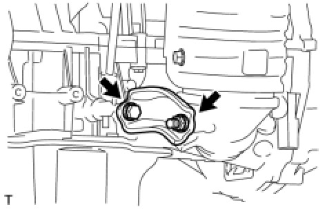
(a) Install the stay with the bolt and nut.
Torque: 44 Nm (449 kgf-cm, 32 ft-lbf)
15. INSTALL OIL LEVEL GAUGE GUIDE
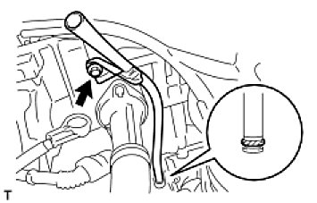
(a) Apply a light coat of engine oil to a new O-ring and install it to the guide.
(b) Install the oil level gauge guide with the bolt.
Torque: 9.0 Nm (92 kgf-cm, 80 in-lbf)
16. INSTALL OIL LEVEL GAUGE SUB-ASSEMBLY
17. INSTALL DRIVE SHAFT BEARING BRACKET
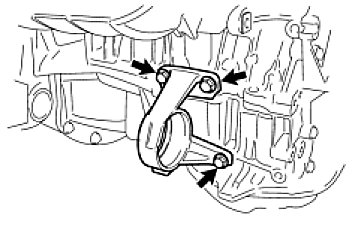
(a) Install the bracket with the 3 bolts.
Torque: 64 Nm (653 kgf-cm, 47 ft-lbf)
18. INSTALL NO. 1 INTAKE MANIFOLD INSULATOR
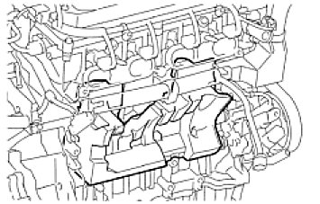
(a) Install the intake manifold insulator onto the cylinder block.
19. INSTALL NO. 2 VENTILATION HOSE
20. INSTALL INTAKE AIR CONTROL VALVE (for PZEV) (Installation)
21. INSTALL INTAKE MANIFOLD
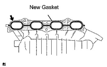
(a) Install a new gasket into the intake manifold.
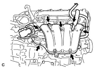
(b) Install the intake manifold with the 5 bolts and 2 nuts.
Torque: 30 Nm (305 kgf-cm, 22 ft-lbf)
22. INSTALL FUEL DELIVERY PIPE WITH INJECTOR (Installation)
23. REMOVE ENGINE STAND
24. INSTALL FLYWHEEL SUB-ASSEMBLY (for Manual Transaxle) (Installation)
25. INSTALL CLUTCH DISC ASSEMBLY (for Manual Transaxle) (Reassembly)
26. INSTALL CLUTCH COVER ASSEMBLY (for Manual Transaxle) (Reassembly)
27. INSTALL DRIVE PLATE & RING GEAR SUB-ASSEMBLY (for Automatic Transaxle) (Installation)
28. INSTALL MANUAL TRANSAXLE ASSEMBLY (for Manual Transaxle)
HINT: (Installation).
29. INSTALL AUTOMATIC TRANSAXLE ASSEMBLY (for Automatic Transaxle)
HINT: (Installation).
30. INSTALL STARTER ASSEMBLY (for Manual Transaxle) (Installation)
31. INSTALL STARTER ASSEMBLY (for Automatic Transaxle) (Installation)
32. INSTALL ENGINE WIRE
33. INSTALL FRONT DRIVE SHAFT ASSEMBLY LH (Installation)
34. INSTALL FRONT DRIVE SHAFT ASSEMBLY RH (Installation)
35. INSTALL FRONT FRAME ASSEMBLY
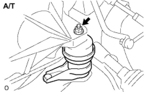
(a) A/T:
Install the engine mounting insulator LH with the nut.
Torque: 95 Nm (969 kgf-cm, 70 ft-lbf)
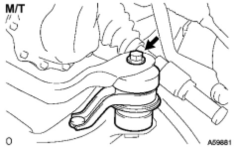
(b) M/T:
Install the engine mounting insulator LH with the bolt.
Torque: 143 Nm (1,459 kgf-cm, 105 ft-lbf)
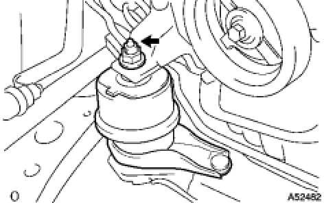
(c) Install the engine mounting insulator RH with the nut.
Torque: 95 Nm (969 kgf-cm, 70 ft-lbf)
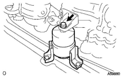
(d) Install the engine mounting insulator FR with the bolt.
Torque: 87 Nm (888 kgf-cm, 64 ft-lbf)
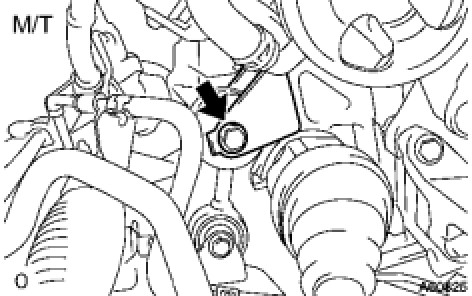
(e) M/T:
Install the engine lateral control rod with the bolt.
Torque: 89 Nm (910 kgf-cm, 66 ft-lbf)
36. INSTALL VANE PUMP ASSEMBLY
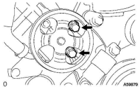
(a) Install the vane pump to the engine with the 2 bolts.
Torque: 43 Nm (439 kgf-cm, 32 ft-lbf)
(b) Connect the oil pressure switch connector.
37. INSTALL ENGINE ASSEMBLY WITH TRANSAXLE
(a) Set the engine assembly with transaxle on the engine lifter.
(b) Install the engine assembly to the vehicle.
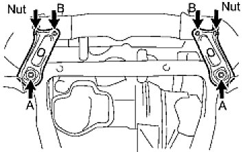
(c) Install the frame side plate LH and RH with the 4 bolts and 2 nuts.
Bolt A - Torque: 85 Nm (867 kgf-cm, 63 ft-lbf)
Bolt B and nut - Torque: 32 Nm (326 kgf-cm, 24 ft-lbf)
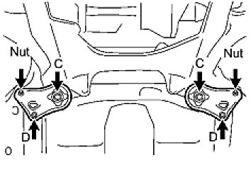
(d) Install the front suspension member brace rear RH and LH with the 4 bolts and 2 nuts.
Bolt C - Torque: 85 Nm (867 kgf-cm, 63 ft-lbf)
Bolt D and nut - Torque: 32 Nm (326 kgf-cm, 24 ft-lbf)
38. INSTALL STEERING SLIDING YOKE (Installation)
39. INSTALL NO. 1 EXHAUST PIPE SUPPORT BRACKET
(a) Install the exhaust pipe support bracket with the 2 bolts.
Torque: 19 Nm (194 kgf-cm, 14 ft-lbf)
40. INSTALL DRIVE PLATE & TORQUE CONVERTER CLUTCH SETTING BOLT (for Automatic Transaxle) (Installation)
41. INSTALL FRONT AXLE ASSEMBLY LH (Installation)
42. INSTALL FRONT AXLE ASSEMBLY RH
HINT: Use the same procedures described for the LH side.
43. INSTALL FRONT SUSPENSION LOWER NO. 1 ARM LH (Installation)
44. INSTALL FRONT SUSPENSION LOWER NO. 1 ARM RH
HINT: Use the same procedures described for the LH side.
45. INSTALL TIE ROD ASSEMBLY LH (Installation)
46. INSTALL TIE ROD ASSEMBLY RH
HINT: Use the same procedures described for the LH side.
47. INSTALL FRONT SPEED SENSOR LH (Installation)
48. INSTALL FRONT SPEED SENSOR RH
Torque: 8.0 Nm (82 kgf-cm, 71 in-lbf)
49. INSTALL FRONT STABILIZER LINK ASSEMBLY LH (Installation)
50. INSTALL FRONT STABILIZER LINK ASSEMBLY RH
HINT: Use the same procedures described for the LH side.
51. INSTALL FRONT AXLE HUB NUT LH (Installation)
52. INSTALL FRONT AXLE HUB NUT RH
HINT: Use the same procedures described for the LH side.
53. INSTALL FRONT EXHAUST PIPE ASSEMBLY
HINT: (Installation).
54. INSTALL COMPRESSOR AND MAGNETIC CLUTCH
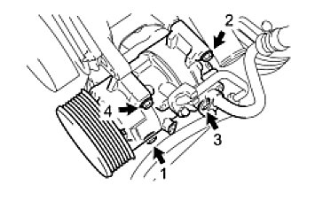
(a) Install the cooler compressor with the 4 bolts.
Torque: 25 Nm (250 kgf-cm, 18 ft-lbf)
NOTE: Tighten the bolts in the order shown in the illustration to install the cooler compressor.
55. INSTALL GENERATOR ASSEMBLY (Installation)
56. CONNECT FUEL TUBE SUB-ASSEMBLY
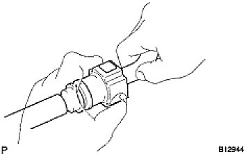
(a) Push in the fuel tube connector to the fuel pipe until the connector makes a "click" sound.
- Check for damage or contamination on the connected part of the pipe.
- Check if the pipe and the connector are securely connected by trying to pull them apart.
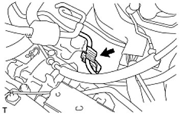
(b) Install the No. 1 fuel pipe clamp.
57. INSTALL CLUTCH RELEASE CYLINDER ASSEMBLY (for Manual Transaxle)
HINT: (Installation).
58. REMOVE CLUTCH ACCUMULATOR ASSEMBLY (for Manual Transaxle)
HINT: (Installation).
59. CONNECT RETURN TUBE SUB-ASSEMBLY
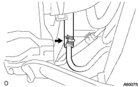
(a) Connect the return tube sub-assembly.
60. CONNECT NO. 1 OIL RESERVOIR TO PUMP HOSE
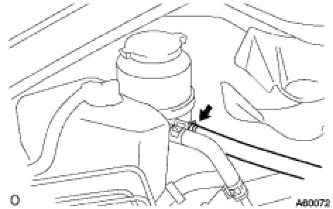
(a) Connect the No. 1 oil reservoir to pump hose.
61. INSTALL TRANSMISSION CONTROL CABLE ASSEMBLY (for Manual Transaxle)
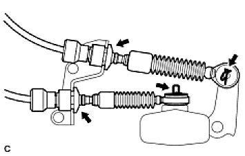
(a) Connect the ends of the 2 cables and install the 2 washers and 2 clips.
(b) Install 2 new clips to the control cable bracket.
62. INSTALL TRANSMISSION CONTROL CABLE ASSEMBLY (for Automatic Transaxle)
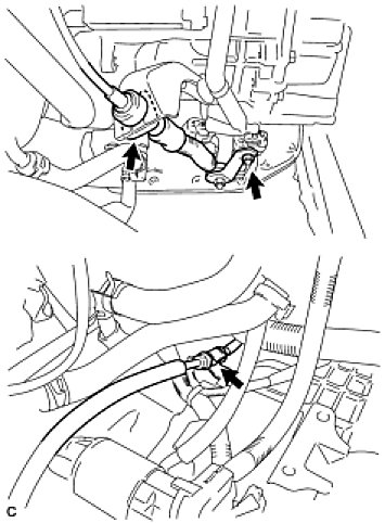
(a) Install a new clip and nut, and connect the control lever.
Torque: 13 Nm (133 kgf-cm, 10 ft-lbf)
(b) Connect the clamp with the cable to the transaxle.
63. CONNECT ENGINE WIRE
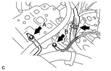
(a) Install the 2 bolts and clamp to the body.
Bolt A - Torque: 8.4 Nm (85 kgf-cm, 74 in-lbf)
Bolt B - Torque: 12 Nm (123 kgf-cm, 9 ft-lbf)
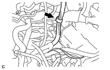
(b) Connect the clamp to the bracket.
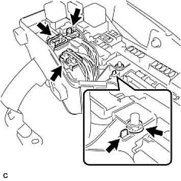
(c) Connect the wire to the engine room junction block. Then, install it with the nut and 3 connectors.
Torque: 8.4 Nm (85 kgf-cm, 74 in-lbf)
64. INSTALL ECM
HINT: (Installation).
65. CONNECT HEATER INLET WATER HOSE
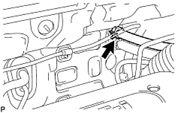
(a) Connect the heater inlet water hose.
66. CONNECT HEATER OUTLET WATER HOSE
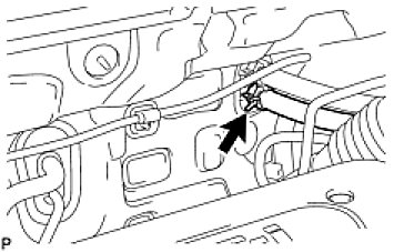
(a) Connect the heater outlet water hose.
67. CONNECT OIL COOLER INLET HOSE (Installation)
68. CONNECT OIL COOLER OUTLET HOSE (Installation)
69. CONNECT RADIATOR HOSE INLET
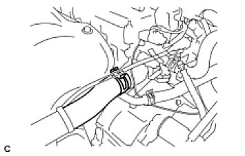
(a) Install the clamp and connect the radiator hose inlet.
70. CONNECT RADIATOR HOSE OUTLET
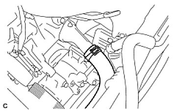
(a) Install the clamp and connect the radiator hose outlet.
71. CONNECT NO. 1 VACUUM HOSE CONNECTOR
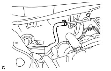
(a) Install the clamp and connect the vacuum hose connector.
72. INSTALL NO. 2 ENGINE MOUNTING BRACKET RH
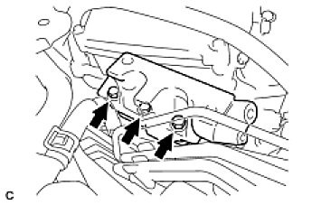
(a) Install the 3 bolts and No. 2 mounting bracket RH.
Torque: 52 Nm (531 kgf-cm, 38 ft-lbf)
73. INSTALL ENGINE MOVING CONTROL ROD SUB-ASSEMBLY
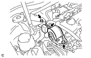
(a) Install the engine moving control rod with the 3 bolts.
Torque: 64 Nm (653 kgf-cm, 47 ft-lbf)
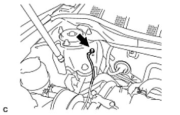
(b) Install the ground cable with the bolt.
Torque: 8.4 Nm (85 kgf-cm, 74 in-lbf)
74. INSTALL NO. 2 ENGINE MOUNTING STAY RH
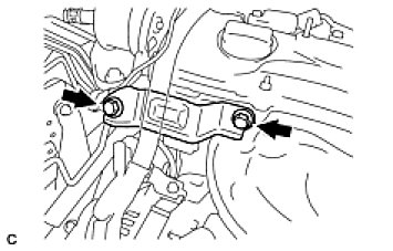
(a) Install the No. 2 mounting stay RH with the 2 bolts.
Torque: 64 Nm (653 kgf-cm, 47 ft-lbf)
75. INSTALL BATTERY
(a) Install the battery and battery tray.
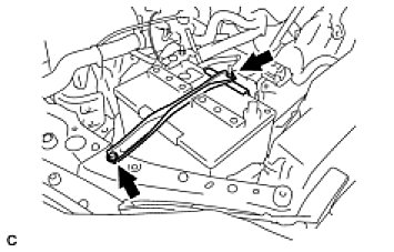
(b) Install the battery clamp with the bolt and nut.
Bolt - Torque: 9.0 Nm (92 kgf-cm, 80 in-lbf)
Nut - Torque: 3.5 Nm (36 kgf-cm, 31 in-lbf)
76. INSTALL AIR CLEANER CASE SUB-ASSEMBLY
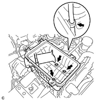
(a) Install the air cleaner case with the 3 bolts.
Torque: 5.0 Nm (51 kgf-cm, 44 in-lbf)
(b) Connect the hose clamp.
77. INSTALL AIR CLEANER CAP SUB-ASSEMBLY (Installation)
78. INSTALL AIR CLEANER INLET ASSEMBLY
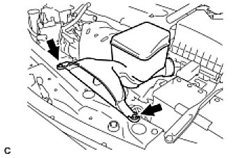
(a) Install the air cleaner inlet with the 2 bolts.
Torque: 5.0 Nm (51 kgf-cm, 44 in-lbf)
79. INSTALL V-RIBBED BELT (Installation)
80. INSTALL COWL TOP PANEL OUTER SUB-ASSEMBLY (Installation)
81. INSTALL WINDSHIELD WIPER LINK ASSEMBLY
HINT: (Installation).
82. INSTALL FRONT WHEEL
Torque: 103 Nm (1,050 kgf-cm, 76 ft-lbf)
83. ADD ENGINE OIL
84. CONNECT CABLE TO NEGATIVE BATTERY TERMINAL
Torque: 6.9 Nm (70 kgf-cm, 61 in-lbf)
85. BLEED CLUTCH LINE (for Manual Transaxle) (Installation)
86. ADD ENGINE COOLANT (Testing and Inspection)
87. ADD MANUAL TRANSAXLE OIL (for Manual Transaxle) (Installation)
88. ADD AUTOMATIC TRANSAXLE FLUID (for Automatic Transaxle) (Installation)
89. ADD POWER STEERING FLUID
90. BLEED POWER STEERING FLUID (Service and Repair)
91. CHECK FOR FUEL LEAKS (Testing and Inspection)
92. CHECK FOR ENGINE OIL LEAKS
93. CHECK FOR ENGINE COOLANT LEAKS (Testing and Inspection)
94. CHECK FOR EXHAUST GAS LEAKS
95. CHECK SHIFT LEVER POSITION (On-Vehicle Inspection)
96. ADJUST FRONT WHEEL ALIGNMENT
HINT: (Service and Repair).
97. CHECK IGNITION TIMING (Engine)
98. CHECK ENGINE IDLE SPEED (Engine)
99. INSPECT CO/HC (Engine)
100.5GINSTALL FRONT FENDER APRON SEAL RH
101.5GINSTALL ENGINE UNDER COVER LH
102.5GINSTALL ENGINE UNDER COVER RH
103.5GINSTALL NO. 1 ENGINE COVER SUB-ASSEMBLY
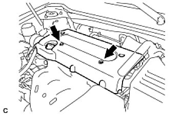
(a) Install the engine cover with the 2 nuts.
Torque: 9.0 Nm (92 kgf-cm, 80 in-lbf)
104.5GCHECK ABS SPEED SENSOR SIGNAL
(a) ABS: (Test Mode Procedure).
(b) VSC (for BOSCH): (Test Mode Procedure).
(c) VSC (for ADVICS): (Test Mode Procedure).