Diagnosis System
CAN COMMUNICATION: CAN COMMUNICATION SYSTEM: DIAGNOSIS SYSTEM
1. BUS CHECK
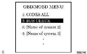
(a) Select "BUS CHECK" from the "OBD/MOBD MENU" screen.
HINT
The ECUs and sensors that are properly connected to the CAN communication system can be displayed using the intelligent tester via CAN VIM.
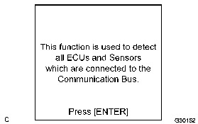
(b) Press "ENTER" on the intelligent tester via CAN VIM.
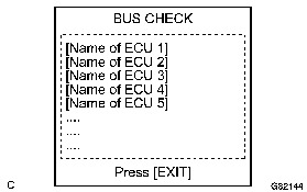
(c) The screen displays the ECUs and sensors that are properly connected to the CAN communication system.
HINT
If any properly connected ECUs or sensors are not displayed, there is a communication stop in the system.
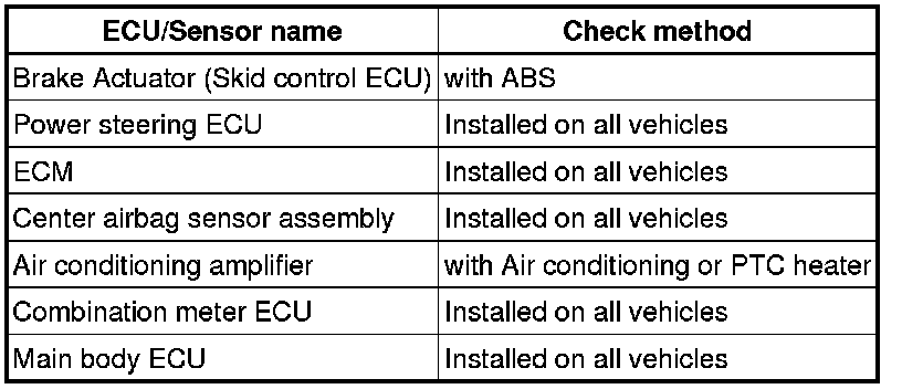
2. CHECK INSTALLED SYSTEMS (ECUs AND SENSORS) THAT ADOPT CAN COMMUNICATION
(a) Systems (ECUs and sensors) that adopt CAN communication vary depending on the vehicle's optional settings. Check which systems (ECUs, sensors) are installed on the vehicle.
3. DTC TABLE BY ECU
HINT
* In the CAN communication system, CAN communication system DTCs output by the ECU can be displayed by using the intelligent tester.
* If CAN communication system DTCs are output, trouble cannot be determined solely from the DTCs. Perform troubleshooting according to "HOW TO PROCEED WITH TROUBLESHOOTING" How to Proceed With Troubleshooting.
(a) BRAKE ACTUATOR (SKID CONTROL ECU)
HINT
DTC communication uses the CAN communication system.

(b) POWER STEERING ECU
HINT
DTC communication uses the SIL Line.

*: For vehicle with ABS only.
(c) COMBINATION METER ASSEMBLY
HINT
DTC communication uses the CAN communication system.

*: For vehicle with ABS only.
(d) AIR CONDITIONING AMPLIFIER
HINT
DTC communication uses the CAN communication system.

(e) MAIN BODY ECU
HINT
The main body ECU is connected to the CAN communication system but CAN communication DTCs are not output.
(f) CENTER AIRBAG SENSOR ASSEMBLY
HINT
The center airbag sensor assembly is connected to the CAN communication system but CAN communication DTCs are not output.
(g) ECM
HINT
The ECM is connected to the CAN communication system but CAN communication DTCs are not output.
4. DTC COMBINATION TABLE
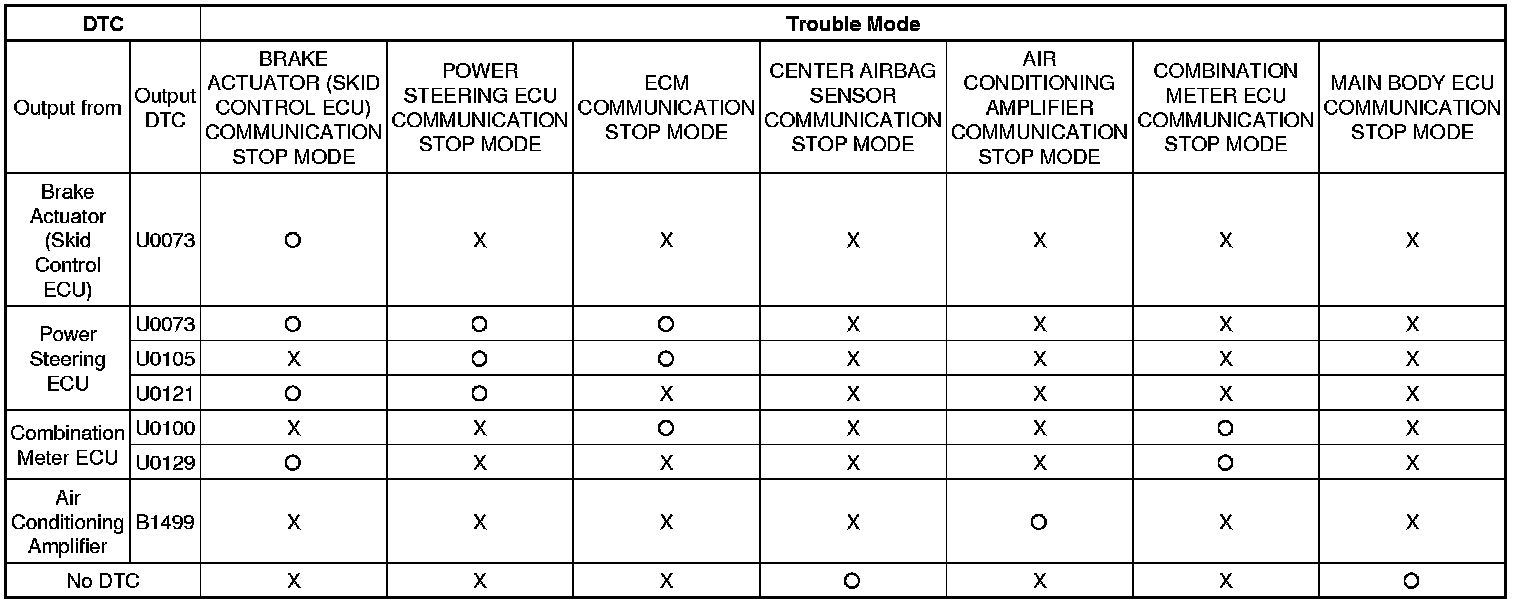
HINT
* o: It is necessary to check for the trouble mode.
* X: Not output
(a) Perform troubleshooting according to the combination of DTCs output.
HINT
* BRAKE ACTUATOR (SKID CONTROL ECU) COMMUNICATION STOP MODE: Brake Actuator (Skid Control ECU) Communication Stop Mode
* POWER STEERING ECU COMMUNICATION STOP MODE: Power Steering ECU Communication Stop Mode
* ECM COMMUNICATION STOP MODE: ECM Communication Stop Mode
* CENTER AIRBAG SENSOR COMMUNICATION STOP MODE: Center Airbag Sensor Communication Stop Mode
* AIR CONDITIONING AMPLIFIER COMMUNICATION STOP MODE: Air Conditioning Amplifier Communication Stop Mode
* COMBINATION METER ECU COMMUNICATION STOP MODE: Combination Meter ECU Communication Stop Mode
* MAIN BODY ECU COMMUNICATION STOP MODE: Main Body ECU Communication Stop Mode