Steering Column
REMOVAL PROCEDURENOTICE: Once the steering column is removed from the vehicle, the column is extremely susceptible to damage. Dropping the column assembly on its end could collapse the steering shaft or loosen the plastic injections that maintain column rigidity. Leaning on the column assembly could cause the jacket to bend or deform. Any of the above damage could impair the columns collapsible design. If it is necessary to remove the steering wheel, refer to Steering Wheel. Under no condition should the end of the shaft be hammered on, as hammering could loosen the plastic injections which maintain column rigidity.
NOTICE: The front wheels of the vehicle must be maintained in the straight ahead position and the steering column must be in the LOCK position before disconnecting the steering column or intermediate shaft. Failure to follow these procedures will cause improper alignment of some components during installation and result in damage to the SIR coil assembly.
NOTICE: When removing the steering wheel, use only the specified steering wheel puller. Do not hammer on the end of the steering column shaft. Hammering could loosen the plastic injections which maintain the steering column rigidity.
IMPORTANT: In the event that deployment occurs, inspect the supplemental inflatable restraint (SIR) coil assembly wire for any signs of scorching, melting, or other damage due to excessive heat. If you find damage to the coil assembly, replace the coil assembly. Refer to Inflatable Restraint Steering Wheel Module Coil Replacement in Air Bags and Seat Belts.
CAUTION: Refer to SIR Handling Caution in Service Precautions.
1. Disable the supplemental inflatable restraint (SIR). Refer to Disabling the SIR System in Air Bags and Seat Belts.
CAUTION: Refer to Battery Disconnect Caution in Service Precautions.
2. Disconnect the negative battery cable.
IMPORTANT: If you are servicing the steering column or any column-mounted component, remove the steering wheel. Refer to Steering Wheel Replacement. If you are removing the steering column in order to gain access to the instrument panel components, leave the steering wheel installed on the column.
3. Remove the steering wheel if needed.
4. Remove the knee bolster. Refer to Knee Bolster Replacement in Instrument Panel, Gauges and Warning Indicators.
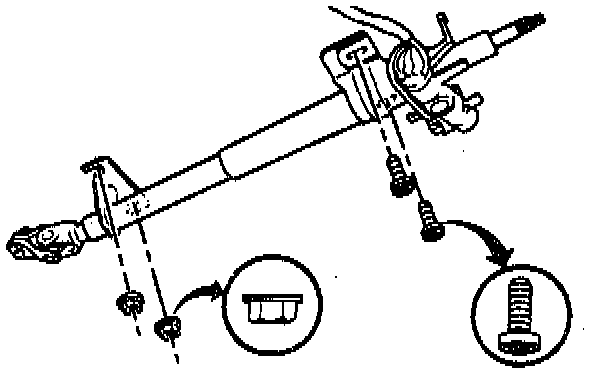
5. Loosen the 2 upper steering column mounting bolts.
6. Slightly lower the steering column.
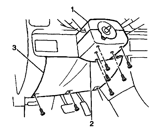
7. Remove the 5 screws from the lower steering column cover (2) in order to remove the upper (1) and the lower (2) covers.
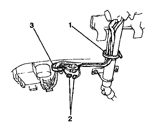
8. Disconnect the SIR coil and combination switch electrical connectors.
9. Loosen the switch electrical harness wire bands (1) on the lower steering column.
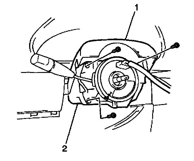
10. Remove the 3 screws in order to remove the SIR coil and combination switch (2) from the steering column.
11. Disconnect all of the ignition wiring connectors at the junction block.
12. Pull the forward section of the driver side floor carpet back.
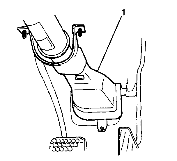
13. Remove the steering shaft joint cover (1) by hand.
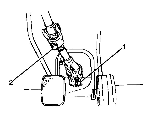
14. Remove the steering shaft joint upper pinch bolt (2), separating the steering shaft from the joint.
15. Remove the lower steering column mounting nuts.
16. Remove the upper steering column mounting bolts.
17. Lower the steering column.
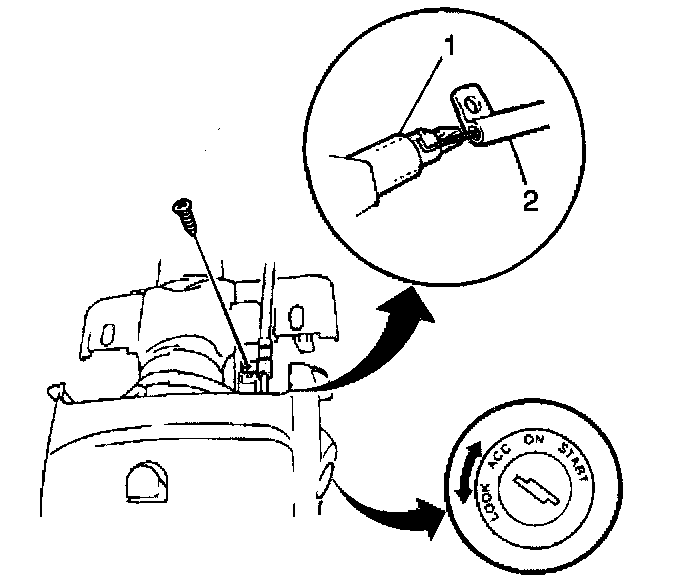
18. Remove the screw (automatic transaxle models only) in order to remove the shift interlock cable (2) from the ignition switch. Refer to Interlock Cable Replacement in Automatic Transaxle.
19. Remove the steering column from the vehicle.
20. Remove the ignition switch from the steering column assembly. Refer to Ignition Switch Replacement - On Vehicle.
INSTALLATION PROCEDURE
IMPORTANT: Do not service the steering shaft and the steering column separately. If you find damage in either the steering shaft or the steering column, replace the unit as an assembly.
1. Install the ignition switch to the steering column assembly.
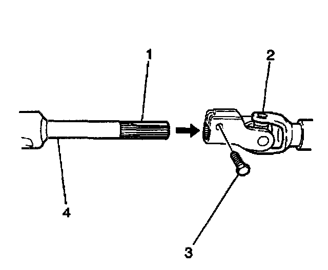
2. Align the flat section of the steering shaft lower spline (1) with the pinch bolt hole in the steering shaft joint (2).
3. Install the steering shaft (4) to the steering shaft joint (2).
4. Secure the steering shaft joint with the steering shaft joint upper pinch bolt (2). Do not fully tighten the bolt.
5. For models with automatic transaxles only, install the shift interlock cable (2) to the ignition switch.
6. Secure the shift interlock cable with the screw (automatic transaxle models only).
7. Position the steering column assembly under the instrument panel.
NOTICE: Refer to Fastener Notice in Service Precautions.
8. Secure the steering column assembly with the 2 upper mounting bolts and the 2 lower mounting nuts. Do not tighten the upper mounting bolts fully.
- Tighten the lower steering column mounting nuts to 14 Nm (10 ft. lbs.).
- Tighten the steering shaft joint upper pinch bolts to 25 Nm (18 ft. lbs.).
9. Install the steering shaft joint cover (1) by hand.
10. Reposition the driver side floor carper.
11. Connect all of the ignition wiring connectors at the junction block.
12. Install the SIR coil and combination switch (2) to the steering column.
13. Secure the SIR coil and combination switch (2) with the 3 screws.
14. Connect the SIR coil and combination switch electrical connectors.
15. Secure the harness to the steering column with the wire bands (1).
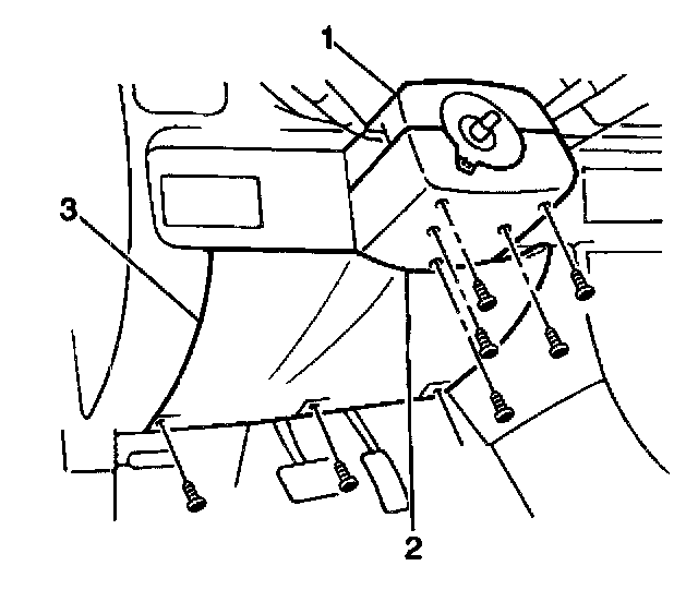
16. Install the upper steering column cover (1) and the lower steering column cover (2).
17. Secure the steering column covers with the 5 screws.
Tighten the upper steering column mounting bolts to 14 Nm (10 ft. lbs.).
18. Install the knee bolster.
19. Install the steering wheel, if you removed the steering wheel.
20. Connect the negative battery cable.
21. Enable the SIR. Refer to Enabling the SIR System in Air Bags and Seat Belts.