Operational Check
Operational CheckThe purpose of the operational check is to confirm that the system operates properly.
CHECKING MEMORY FUNCTION
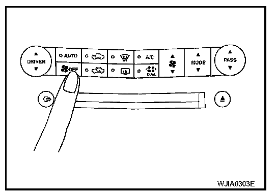
1. Set the temperature to 90 degrees F or 32 degrees C.
2. Press OFF switch.
3. Turn ignition switch OFF.
4. Turn ignition switch ON.
5. Press the AUTO switch.
6. Confirm that the set temperature remains at previous temperature.
7. Press OFF switch.
If NG, go to trouble diagnosis procedure for "Memory Function".
If OK, continue with next check.
CHECKING BLOWER
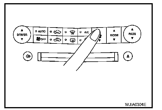
1. Press top of fan control switch. Blower should operate on low speed. The fan symbol should have one blade lit.
2. Press top of fan control switch again, and continue checking blower speed and fan symbol until all speeds are checked.
3. Leave blower on maximum speed.
If NG, go to trouble diagnosis procedure for "DIAGNOSTIC PROCEDURE FOR BLOWER MOTOR"
If OK, continue with next check.
CHECKING DISCHARGE AIR
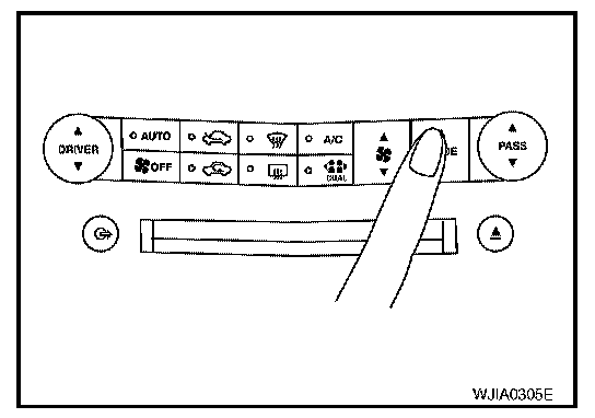
1. Press MODE switch four times and (DEF) switch.
2. Each position indicator should change shape.
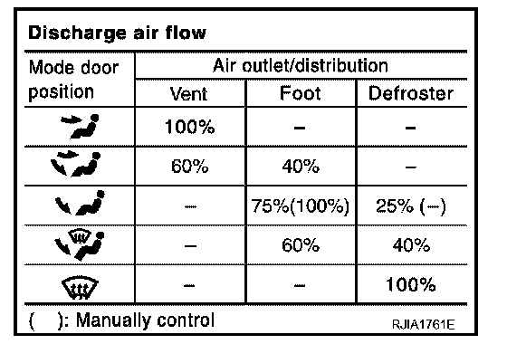
3. Confirm that discharge air comes out according to the air distribution table. Refer to "Discharge Air Flow".
Mode door position is checked in the next step.
If NG, go to trouble diagnosis procedure for ATC-58, "Mode Door Motor Circuit". Mode Door Motor Circuit
If OK, continue with next check.
NOTE: Confirm that the compressor clutch is engaged (sound or visual inspection) and intake door position is at (FRE) when the (DEF) or (D/F) is selected.
CHECKING RECIRCULATION
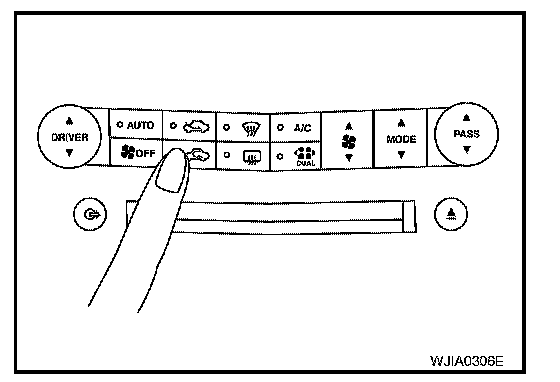
1. Press recirculation (REC) switch one time. Recirculation indicator should illuminate.
2. Press fresh (FRE) switch one time. Fresh indicator should illuminate.
3. Listen for intake door position change (you should hear blower sound change slightly).
If NG, go to trouble diagnosis procedure for ATC-64, "Intake Door Motor Circuit". Intake Door Motor Circuit
If OK, continue with next check.
NOTE: Confirm that the compressor clutch is engaged (sound or visual inspection) and intake door position is at (FRE) when the (DEF) or (D/F) is selected.
CHECKING TEMPERATURE DECREASE
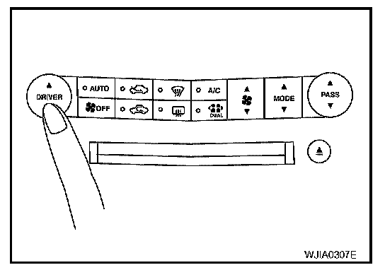
1. Press bottom of temperature switch (driver side) until 16 degrees C (60 degrees F) is displayed.
2. Check for cold air at discharge air outlets.
If NG, go to trouble diagnosis procedure for ATC-79, "Insufficient Cooling". Insufficient Cooling
If OK, continue with next check.
CHECKING TEMPERATURE INCREASE
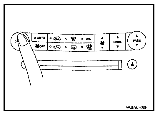
1. Press top of temperature switch (driver side) until 32 degrees C (90 degrees F) is displayed.
2. Check for hot air at discharge air outlets.
If NG, go to trouble diagnosis procedure for ATC-86, "Insufficient Heating". Insufficient Heating
If OK, continue with next check.
CHECK A/C SWITCH
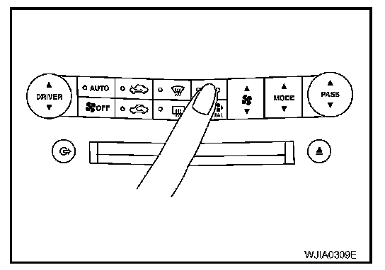
1. Press A/C switch when AUTO switch is ON.
2. A/C switch indicator will turn ON.
- Confirm that the compressor clutch engages (sound or visual inspection).
If NG, go to trouble diagnosis procedure for ATC-73, "Magnet Clutch Circuit". Magnet Clutch Circuit
If OK, continue with next check.
CHECKING AUTO MODE
Inspection Flow:
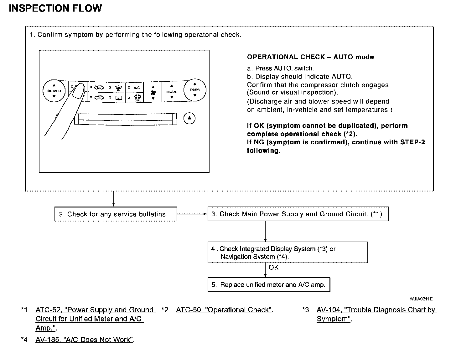
1. Press AUTO switch.
2. Display should indicate AUTO.
- Confirm that the compressor clutch engages (sound or visual inspection). (Discharge air and blower speed will depend on ambient, in-vehicle, and set temperatures.)
If NG, go to trouble diagnosis procedure for ATC-52, "Power Supply and Ground Circuit for Unified Meter and A/C Amp.", Power Supply and Ground Circuit For Unified Meter and A/C Amp. then if necessary, trouble diagnosis procedure for "Magnet Clutch Circuit".
If all operational checks are OK (symptom cannot be duplicated), go to malfunction Simulation Tests in ATC-32, "How to Perform Trouble Diagnosis for Quick and Accurate Repair" Diagnosis and Repair Workflow and perform tests as out lined to simulate driving conditions environment. If symptom appears, refer to ATC-32, "How to Perform Trouble Diagnosis for Quick and Accurate Repair", "SYMPTOM TABLE" Symptom Chart and perform applicable trouble diagnosis procedures.