Inspection Procedure I-3
Flasher Timer: The right or left turn-signal light does not illuminate.Turn-signal Light Circuit Part 1:
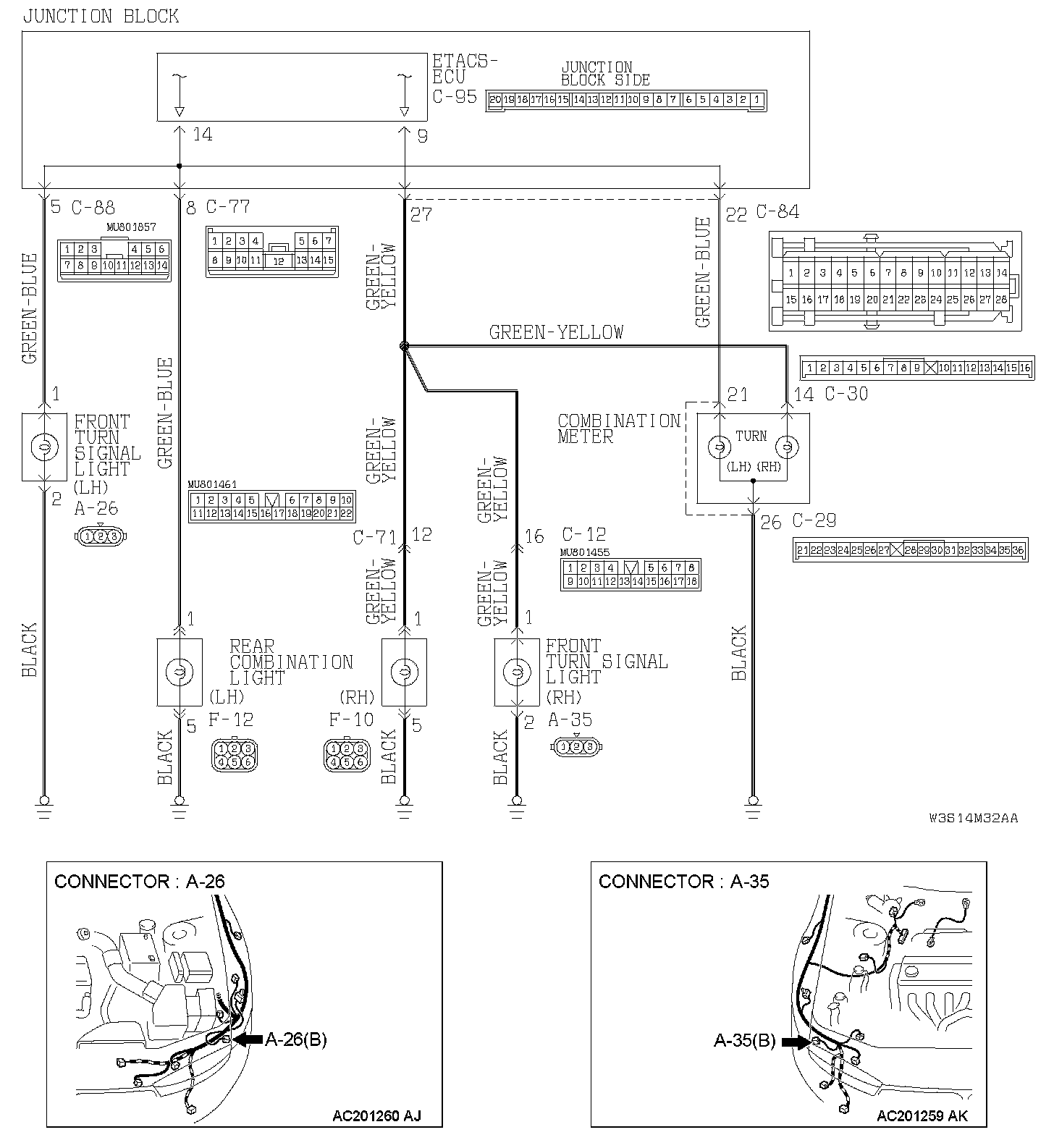
Turn-signal Light Circuit Part 2:
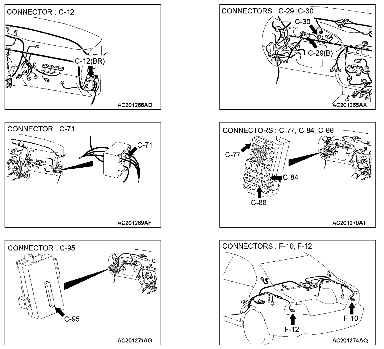
TECHNICAL DESCRIPTION (COMMENT)
If the right or left turn-signal light does not illuminate, their bulb may be defective.
TROUBLESHOOTING HINTS
- The turn-signal light bulb may be defective
- The wiring harness or connectors may have loose, corroded, or damaged terminals, or terminals pushed back in the connector
DIAGNOSIS
Required Special Tool:
- MB991223: Harness Set
STEP 1. Check the hazard warning light.
Q: Which turn-signal light does not illuminate?
front turn-signal light (LH): Go to Step 2.
front turn-signal light (RH): Go to Step 8.
rear combination light (LH): Go to Step 14.
rear combination light (RH): Go to Step 20.
combination meter (LH) : Go to Step 26.
combination meter (RH): Go to Step 28.
Combination meter (both right and left): Go to Step 30.
LH side only : Refer to Inspection Procedure I-1 "Turn-signal lights do not flash when the turn-signal light switch is turned on."
RH side only : Refer to Inspection Procedure I-1 "Turn-signal lights do not flash when the turn-signal light switch is turned on."
Both LH and RH sides : Refer to Inspection Procedure I-2 "Hazard warning light."
STEP 2. Check the front turn-signal light bulb (LH).
1. Remove the front turn-signal (LH) light bulb.
2. Verify that the front turn-signal light bulb (LH) is not damaged or burned out.
Q: Is the front turn-signal (LH) light bulb in good condition?
YES: Go to Step 3.
NO: Replace the front turn-signal (LH) light bulb. Verify that the turn-signal lights illuminate normally.
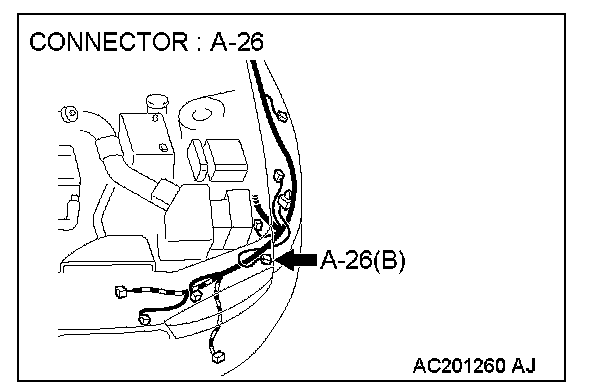
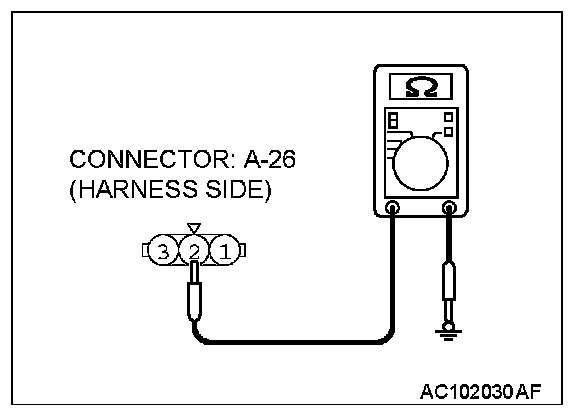
STEP 3. Check the ground circuit to the ETACS-ECU. Test at front combination light (LH) connector A-26.
1. Disconnect front combination light (LH) connector A-26 and measure the resistance available at the wiring harness side of the connector.
2. Measure the resistance value between terminal 2 and ground.
- The resistance should measure 2 ohms or less.
Q: Is the measured resistance 2 ohms or less?
YES: Go to Step 6.
NO: Go to Step 4.
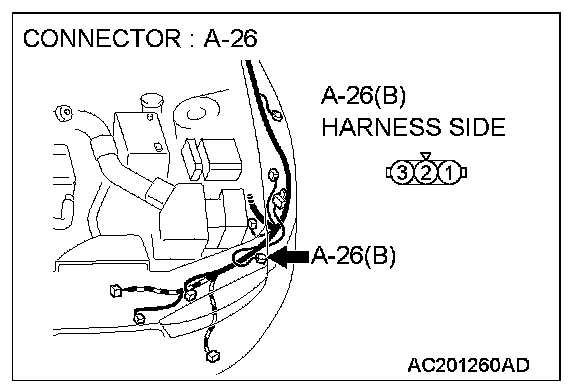
STEP 4. Check front combination light (LH) connector A-26 for loose, corroded or damaged terminals, or terminals pushed back in the connector.
Q: Is front combination light (LH) connector A-26 in good condition?
YES: Go to Step 5.
NO: Repair or replace the damaged component(s). Refer to Harness Connector Inspection. Verify that the turn-signal lights illuminate normally.
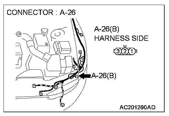
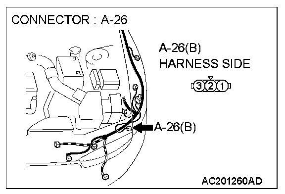
STEP 5. Check the wiring harness between front combination light (LH) connector A-26 (terminal 2) and ground.
Q: Is the wiring harness between front combination light (LH) connector A-26 (terminal 2) and the ground in good condition?
YES: Replace the front combination light socket (LH). Verify that the turn-signal lights illuminate normally.
NO: The wiring harness may be damaged or the connector(s) may have loose, corroded or damaged terminals, or terminals pushed back in the connector. Repair the wiring harness as necessary. Verify that the turn-signal lights illuminate normally.
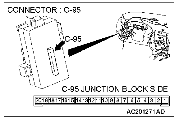
STEP 6. Check front combination light (LH) connector A-26 and ETACS-ECU connector C-95 for loose, corroded or damaged terminals, or terminals pushed back in the connector.
Q: Are front combination light (LH) connector A-26 and ETACS-ECU connector C-95 in good condition?
YES: Go to Step 7.
NO: Repair or replace the damaged component(s). Refer to Harness Connector Inspection. Verify that the turn-signal lights illuminate normally.
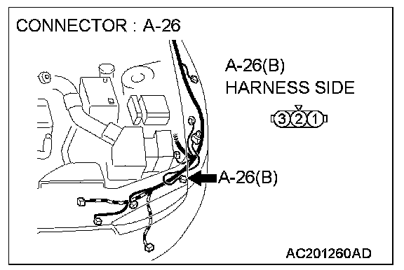
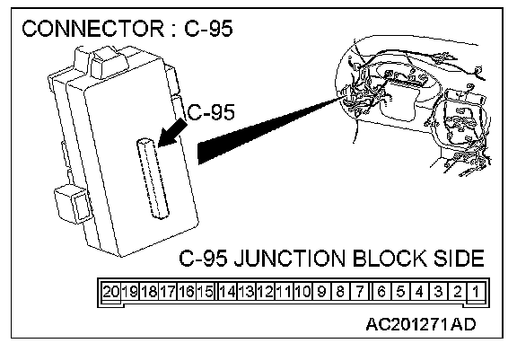
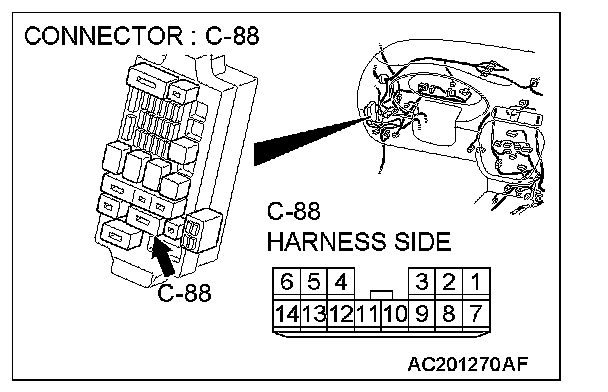
STEP 7. Check the wiring harness between front combination light (LH) connector A-26 (terminal 1) and ETACS-ECU connector C-95 (terminal 14).
NOTE: Also check junction block connector C-88 for loose, corroded, or damaged terminals, or terminals pushed back in the connector. If junction block connector C-88 is damaged, Repair or replace the damaged component(s) as described in Harness Connector Inspection.
Q: Is the wiring harness between front combination light (LH) connector A-26 (terminal 1) and ETACS-ECU connector C-95 (terminal 14) in good condition?
YES: Replace the front combination light socket (LH). Verify that the turn-signal lights illuminate normally.
NO: The wiring harness may be damaged or the connector(s) may have loose, corroded or damaged terminals, or terminals pushed back in the connector. Repair the wiring harness as necessary. Verify that the turn-signal lights illuminate normally.
STEP 8. Check the front turn-signal light bulb (RH).
1. Remove the front turn-signal (RH) light bulb.
2. Verify that the front turn-signal light bulb (RH) is not damaged or burned out.
Q: Is the front turn-signal (RH) light bulb in good condition?
YES: Go to Step 9.
NO: Replace the front turn-signal (RH) light bulb. Verify that the turn-signal lights illuminate normally.
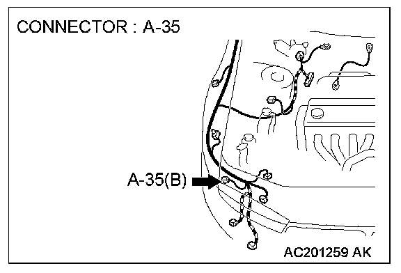
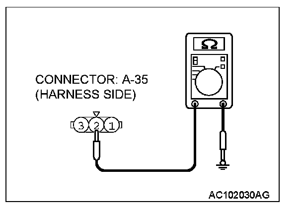
STEP 9. Check the ground circuit to the front combination light (RH). Test at front combination light (RH) connector A-35.
1. Disconnect front combination light (RH) connector A-35 and measure the resistance available at the wiring harness side of the connector.
2. Measure the resistance value between terminal 2 and ground.
- The resistance should measure 2 ohms or less.
Q: Is the measured resistance 2 ohms or less?
YES: Go to Step 12.
NO: Go to Step 10.
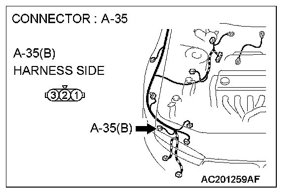
STEP 10. Check front combination light (RH) connector A-35 for loose, corroded or damaged terminals, or terminals pushed back in the connector.
Q: Is front combination light (RH) connector A-35 in good condition?
YES: Go to Step 11.
NO: Repair or replace the damaged component(s). Refer to Harness Connector Inspection. Verify that the turn-signal lights illuminate normally.
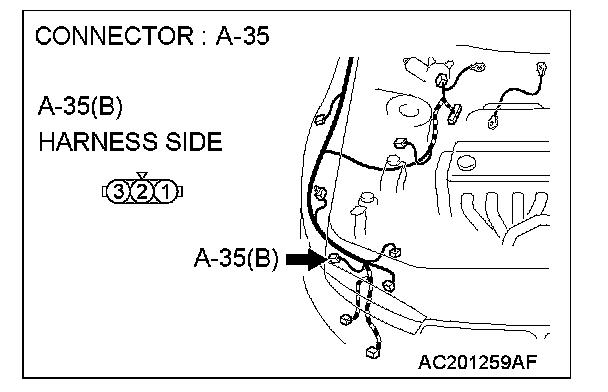
STEP 11. Check the wiring harness between front combination light (RH) connector A-35 (terminal 2) and ground.
Q: Is the wiring harness between front combination light (RH) connector A-35 (terminal 2) and the ground in good condition?
YES: Replace the front combination light socket (RH). Verify that the turn-signal lights illuminate normally.
NO: The wiring harness may be damaged or the connector(s) may have loose, corroded or damaged terminals, or terminals pushed back in the connector. Repair the wiring harness as necessary. Verify that the turn-signal lights illuminate normally.
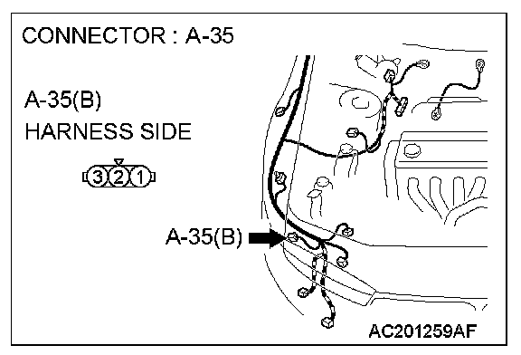
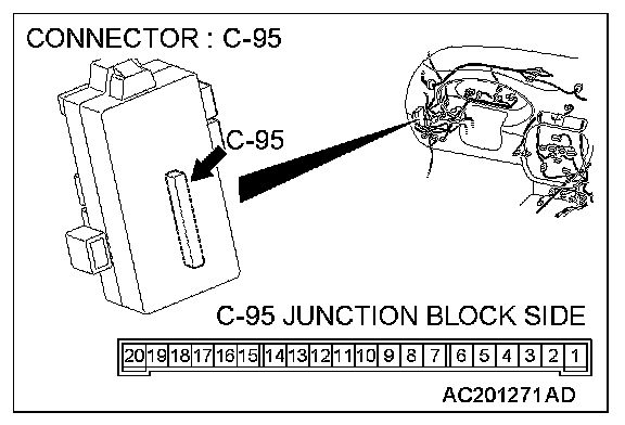
STEP 12. Check front combination light (RH) connector A-35 and ETACS-ECU connector C-95 for loose, corroded or damaged terminals, or terminals pushed back in the connector.
Q: Are front combination light (RH) connector A-35 and ETACS-ECU connector C-95 in good condition?
YES: Go to Step 13.
NO: Repair or replace the damaged component(s). Refer to Harness Connector Inspection. Verify that the turn-signal lights illuminate normally.
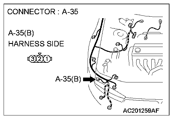
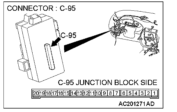
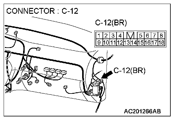
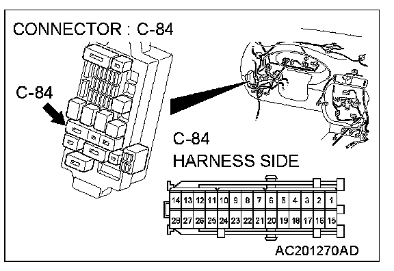
STEP 13. Check the wiring harness between front combination light (RH) connector A-35 (terminal 1) and ETACS-ECU connector C-95 (terminal 9).
NOTE: Also check junction block connector C-84 and intermediate connector C-12 for loose, corroded, or damaged terminals, or terminals pushed back in the connector. If junction block connector C-84 or intermediate connector C-12 is damaged, repair or replace the damaged component(s) as described in Harness Connector Inspection.
Q: Is the wiring harness between front combination light (RH) connector A-35 (terminal 1) and ETACS-ECU connector C-95 (terminal 9) in good condition?
YES: Replace the front combination light socket (RH). Verify that the turn-signal lights illuminate normally.
NO: The wiring harness may be damaged or the connector(s) may have loose, corroded or damaged terminals, or terminals pushed back in the connector. Repair the wiring harness as necessary. Verify that the turn-signal lights illuminate normally.
STEP 14. Check the rear turn-signal light bulb (LH).
1. Remove the rear turn-signal (LH) light bulb.
2. Verify that the rear turn-signal light bulb (LH) is not damaged or burned out.
Q: Is the rear turn-signal (LH) light bulb in good condition?
YES: Go to Step 15.
NO: Replace the rear turn-signal (LH) light bulb. Verify that the turn-signal lights illuminate normally.
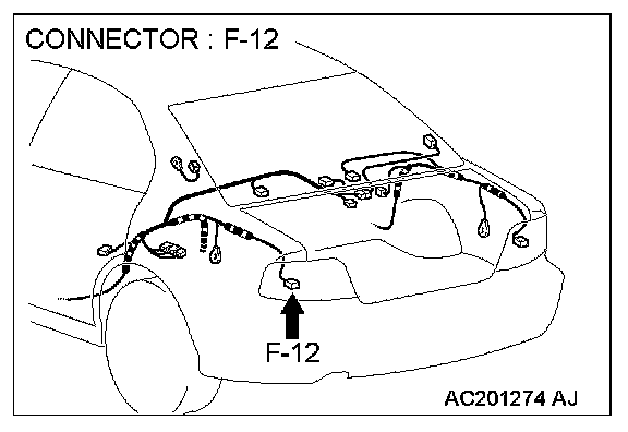
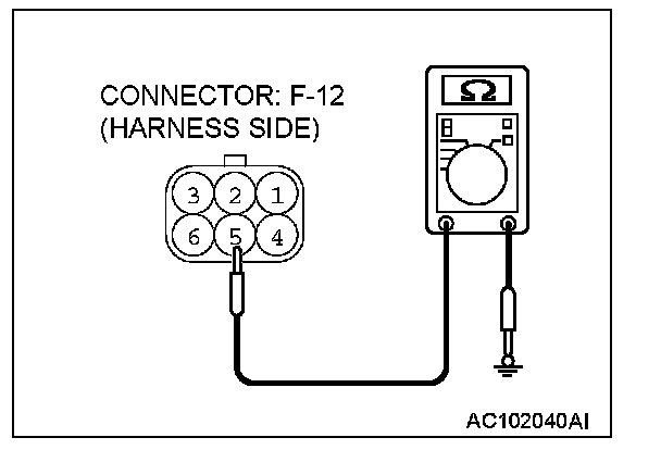
STEP 15. Check the ground circuit to the rear combination light (LH). Test at rear combination light (LH) connector F-12.
1. Disconnect rear combination light (LH) connector F-12 and measure the resistance available at the wiring harness side of the connector.
2. Measure the resistance value between terminal 5 and ground.
- The resistance should measure 2 ohms or less.
Q: Is the measured resistance 2 ohms or less?
YES: Go to Step 18.
NO: Go to Step 16.
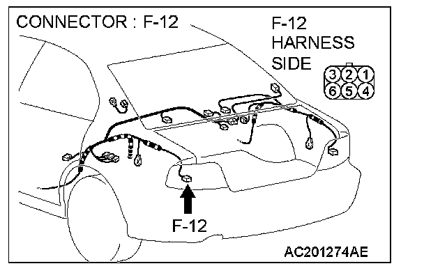
STEP 16. Check rear combination light (LH) connector F-12 for loose, corroded or damaged terminals, or terminals pushed back in the connector.
Q: Is rear combination light (LH) connector F-12 in good condition?
YES: Go to Step 17.
NO: Repair or replace the damaged component(s). Refer to Harness Connector Inspection. Verify that the turn-signal lights illuminate normally.
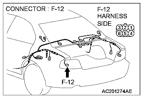
STEP 17. Check the wiring harness between rear combination light (LH) connector F-12 (terminal 5) and ground.
Q: Is the wiring harness between rear combination light (LH) connector F-12 (terminal 5) and the ground in good condition?
YES: Replace the rear combination light socket assembly (LH). Verify that the turn-signal lights illuminate normally.
NO: The wiring harness may be damaged or the connector(s) may have loose, corroded or damaged terminals, or terminals pushed back in the connector. Repair the wiring harness as necessary. Verify that the turn-signal lights illuminate normally.
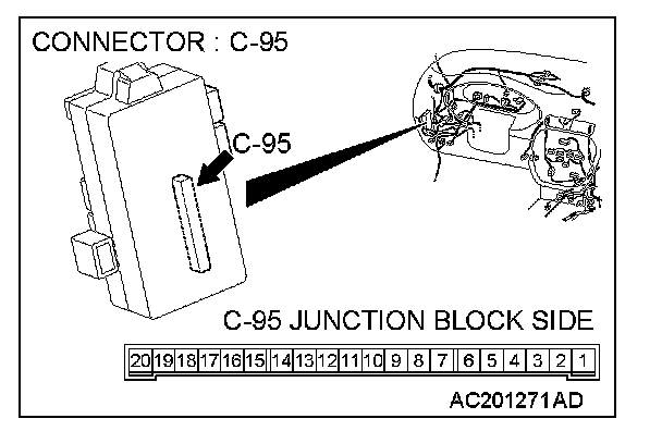
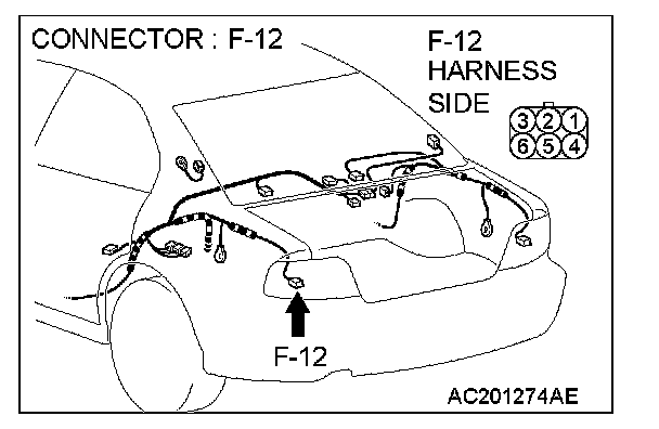
STEP 18. Check rear combination light (LH) connector F-12 and ETACS-ECU connector C-95 for loose, corroded or damaged terminals, or terminals pushed back in the connector.
Q: Are rear combination light (LH) connector F-12 and ETACS-ECU connector C-95 in good condition?
YES: Go to Step 19.
NO: Repair or replace the damaged component(s). Refer to Harness Connector Inspection. Verify that the turn-signal lights illuminate normally.
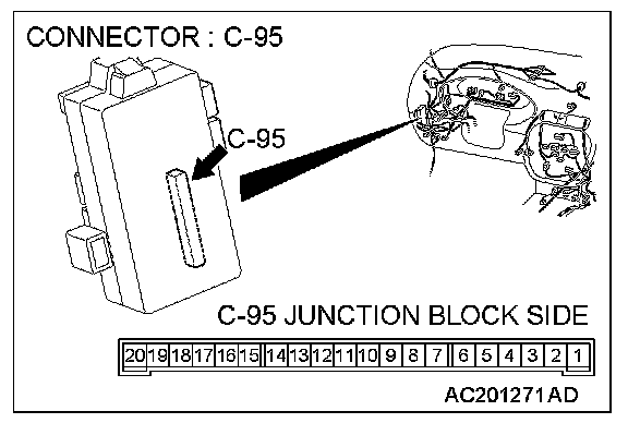
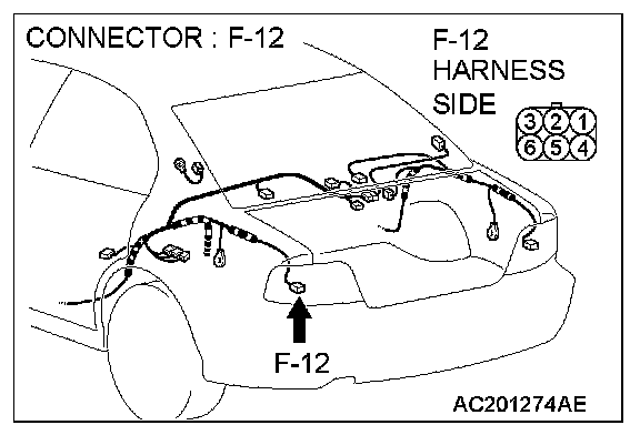
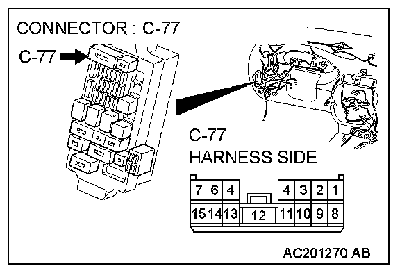
STEP 19. Check the wiring harness between rear combination light (LH) connector F-12 (terminal 1) and ETACS-ECU connector C-95 (terminal 14).
NOTE: Also check junction block connector C-77 for loose, corroded, or damaged terminals, or terminals pushed back in the connector. If junction block connector C-77 is damaged, Repair or replace the damaged component(s) as described in Harness Connector Inspection.
Q: Is the wiring harness between rear combination light (LH) connector F-12 (terminal 1) and ETACS-ECU connector C-95 (terminal 14) in good condition?
YES: Replace the rear combination light socket assembly (LH). Verify that the turn-signal lights illuminate normally.
NO: The wiring harness may be damaged or the connector(s) may have loose, corroded or damaged terminals, or terminals pushed back in the connector. Repair the wiring harness as necessary. Verify that the turn-signal lights illuminate normally.
STEP 20. Check the rear turn-signal light bulb (RH).
1. Remove the rear turn-signal (RH) light bulb.
2. Verify that the rear turn-signal light bulb (RH) is not damaged or burned out.
Q: Is the rear turn-signal (RH) light bulb in good condition?
YES: Go to Step 21.
NO: Replace the rear turn-signal (RH) light bulb. Verify that the turn-signal lights illuminate normally.
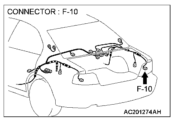
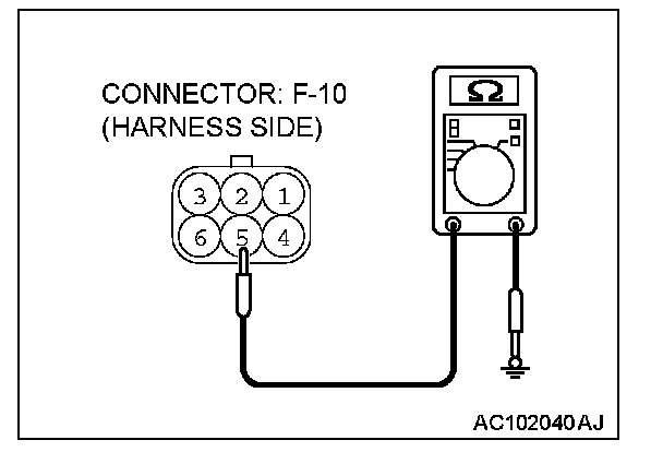
STEP 21. Check the ground circuit to the rear turn-signal light (RH). Test at rear combination light (RH) connector F-10.
1. Disconnect rear combination light (RH) connector F-10 and measure the resistance available at the harness side of the connector.
2. Measure the resistance value between terminal 5 and ground.
- The resistance should measure 2 ohms or less.
Q: Is the measured resistance 2 ohms or less?
YES: Go to Step 24.
NO: Go to Step 22.
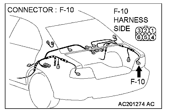
STEP 22. Check rear combination light (RH) connector F-10 for loose, corroded or damaged terminals, or terminals pushed back in the connector.
Q: Is rear combination light (RH) connector F-10 in good condition?
YES: Go to Step 23.
NO: Repair or replace the damaged component(s). Refer to Harness Connector Inspection. Verify that the turn-signal lights illuminate normally.
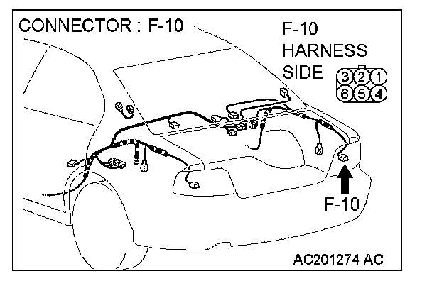
STEP 23. Check the wiring harness between rear combination light (RH) connector F-10 (terminal 5) and ground.
Q: Is the wiring harness between rear combination light (RH) connector F-10 (terminal 5) and the ground in good condition?
YES: Replace the rear combination light socket assembly (RH). Verify that the turn-signal lights illuminate normally.
NO: The wiring harness may be damaged or the connector(s) may have loose, corroded or damaged terminals, or terminals pushed back in the connector. Repair the wiring harness as necessary. Verify that the turn-signal lights illuminate normally.
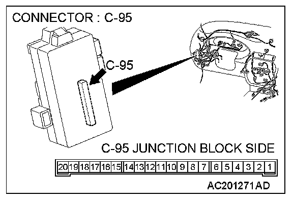
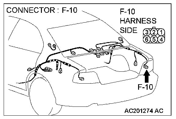
STEP 24. Check rear combination light (RH) connector F-10 and ETACS-ECU connector C-95 for loose, corroded or damaged terminals, or terminals pushed back in the connector.
Q: Are rear combination light (RH) connector F-10 and ETACS-ECU connector C-95 in good condition?
YES: Go to Step 25.
NO: Repair or replace the damaged component(s). Refer to Harness Connector Inspection. Verify that the turn-signal lights illuminate normally.
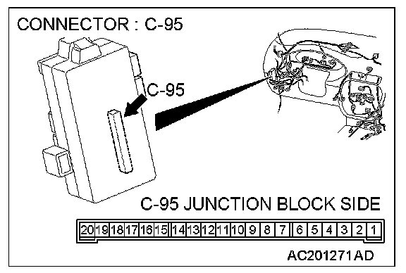
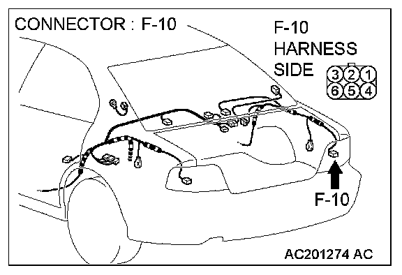
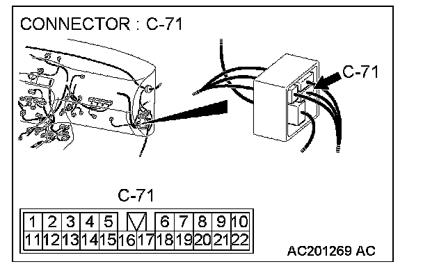
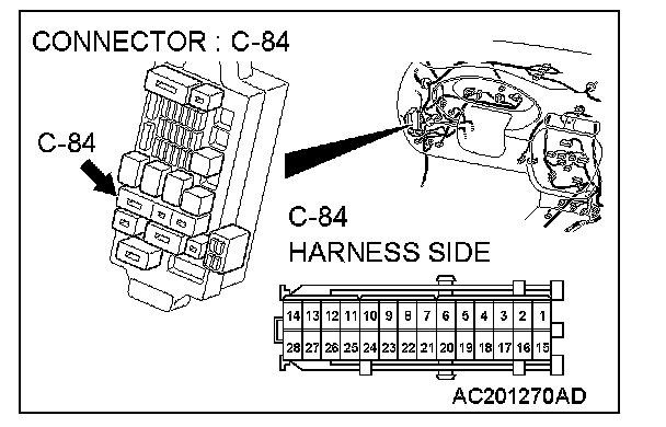
STEP 25. Check the wiring harness between rear combination light (RH) connector F-10 (terminal 1) and ETACS-ECU connector C-95 (terminal 9).
NOTE: Also check junction block connector C-84 and intermediate connector C-71 for loose, corroded, or damaged terminals, or terminals pushed back in the connector. If junction block connector C-84 or intermediate connector C-71 is damaged, repair or replace the damaged component(s) as described in Harness Connector Inspection.
Q: Is the wiring harness between rear combination light (RH) connector F-10 (terminal 1) and ETACS-ECU connector C-95 (terminal 9) in good condition?
YES: Replace the rear combination light socket assembly (RH). Verify that the turn-signal lights illuminate normally.
NO: The wiring harness may be damaged or the connector(s) may have loose, corroded or damaged terminals, or terminals pushed back in the connector. Repair the wiring harness as necessary. Verify that the turn-signal lights illuminate normally.
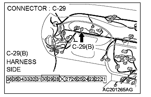
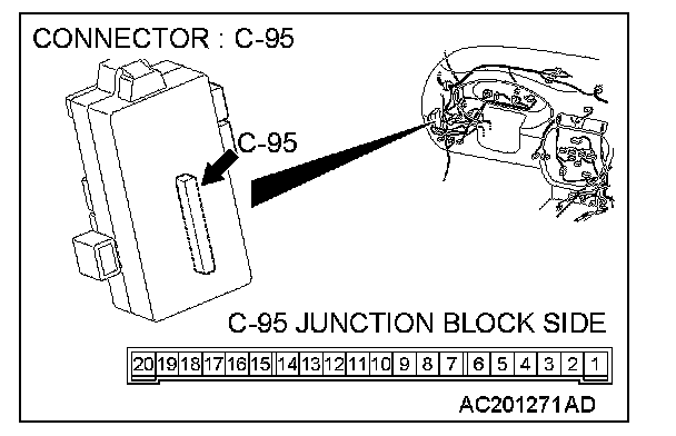
STEP 26. Check combination meter connector C-29 and ETACS-ECU connector C-95 for loose, corroded or damaged terminals, or terminals pushed back in the connector.
Q: Are combination meter connector C-29 and ETACS-ECU connector C-95 in good condition?
YES: Go to Step 27.
NO: Repair or replace the damaged component(s). Refer to Harness Connector Inspection. Verify that the turn-signal lights illuminate normally.
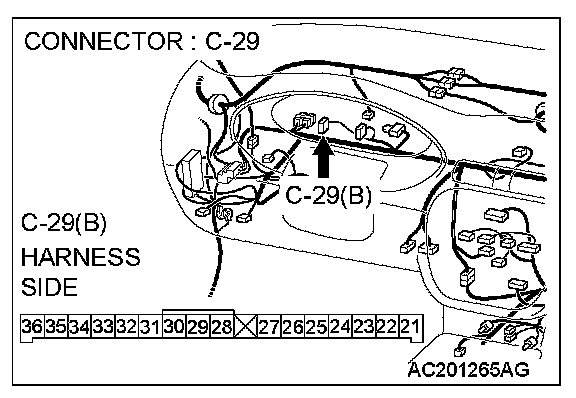
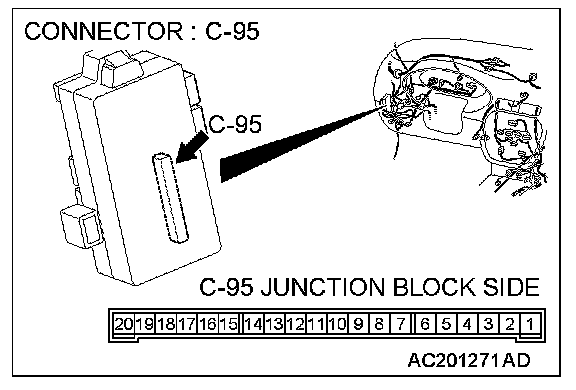
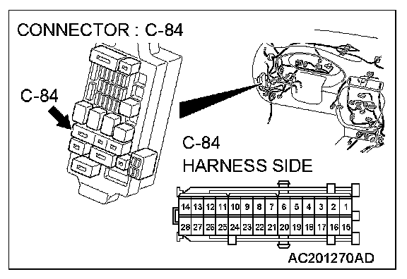
STEP 27. Check the wiring harness between combination meter connector C-29 (terminal 21) and ETACS-ECU connector C-95 (terminal 14).
NOTE: Also check junction block connector C-84 for loose, corroded, or damaged terminals, or terminals pushed back in the connector. If junction block connector C-84 is damaged, Repair or replace the damaged component(s) as described in Harness Connector Inspection.
Q: Is the wiring harness between combination meter connector C-29 (terminal 21) and ETACS-ECU connector C-95 (terminal 14) in good condition?
YES: Replace the combination meter. Verify that the turn-signal lights illuminate normally.
NO: The wiring harness may be damaged or the connector(s) may have loose, corroded or damaged terminals, or terminals pushed back in the connector. Repair the wiring harness as necessary. Verify that the turn-signal lights illuminate normally.
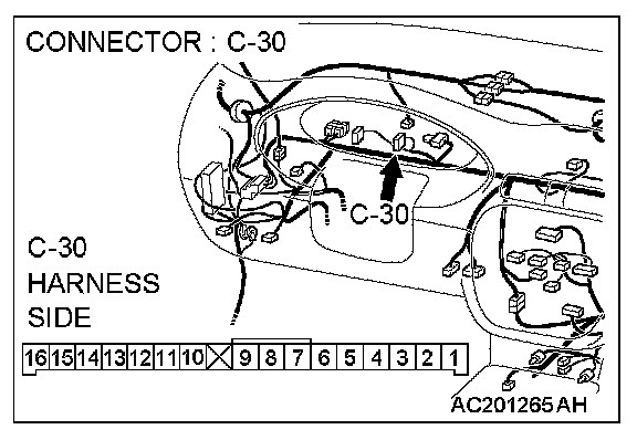
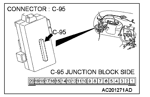
STEP 28. Check combination meter connector C-30 and ETACS-ECU connector C-95 for loose, corroded or damaged terminals, or terminals pushed back in the connector.
Q: Are combination meter connector C-30 and ETACS-ECU connector C-95 in good condition?
YES: Go to Step 29.
NO: Repair or replace the damaged component(s). Refer to Harness Connector Inspection. Verify that the turn-signal lights illuminate normally.
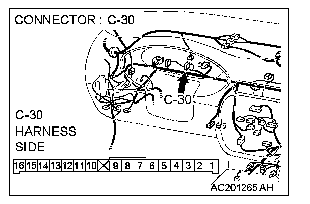
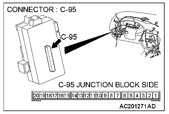
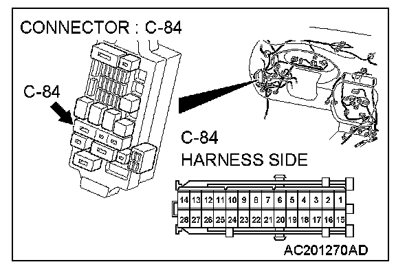
STEP 29. Check the wiring harness between combination meter connector C-30 (terminal 14) and ETACS-ECU connector C-95 (terminal 9).
NOTE: Also check junction block connector C-84 for loose, corroded, or damaged terminals, or terminals pushed back in the connector. If junction block connector C-84 is damaged, Repair or replace the damaged component(s) as described in Harness Connector Inspection.
Q: Is the wiring harness between combination meter connector C-30 (terminal 14) and ETACS-ECU connector C-95 (terminal 9) in good condition?
YES: Replace the combination meter. Verify that the turn-signal lights illuminate normally.
NO: The wiring harness may be damaged or the connector(s) may have loose, corroded or damaged terminals, or terminals pushed back in the connector. Repair the wiring harness as necessary. Verify that the turn-signal lights illuminate normally.
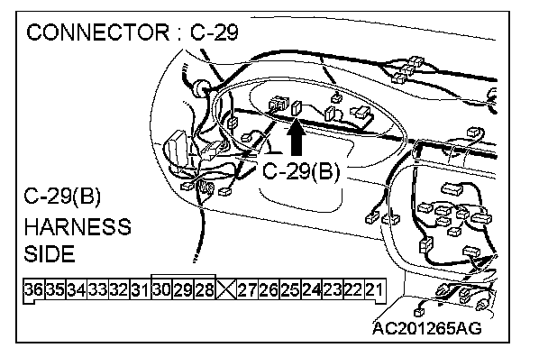
STEP 30. Check combination meter connector C-29 for loose, corroded or damaged terminals, or terminals pushed back in the connector.
Q: Is combination meter connector C-29 in good condition?
YES: Go to Step 31.
NO: Repair or replace the damaged component(s). Refer to Harness Connector Inspection. Verify that the turn-signal lights illuminate normally.
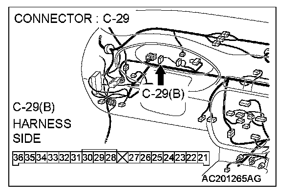
STEP 31. Check the wiring harness between combination meter connector C-29 (terminal 26) and ground.
Q: Is the wiring harness between combination meter connector C-29 (terminal 26) and ground in good condition?
YES: Replace the combination meter. Verify that the turn-signal lights illuminate normally.
NO: The wiring harness may be damaged or the connector(s) may have loose, corroded or damaged terminals, or terminals pushed back in the connector. Repair the wiring harness as necessary. Verify that the turn-signal lights illuminate normally.