Inspection Procedure A-1
Communication with the SWS monitor kit is not possible.Scan Tool Communication ETACS-ECU Ground Circuit:
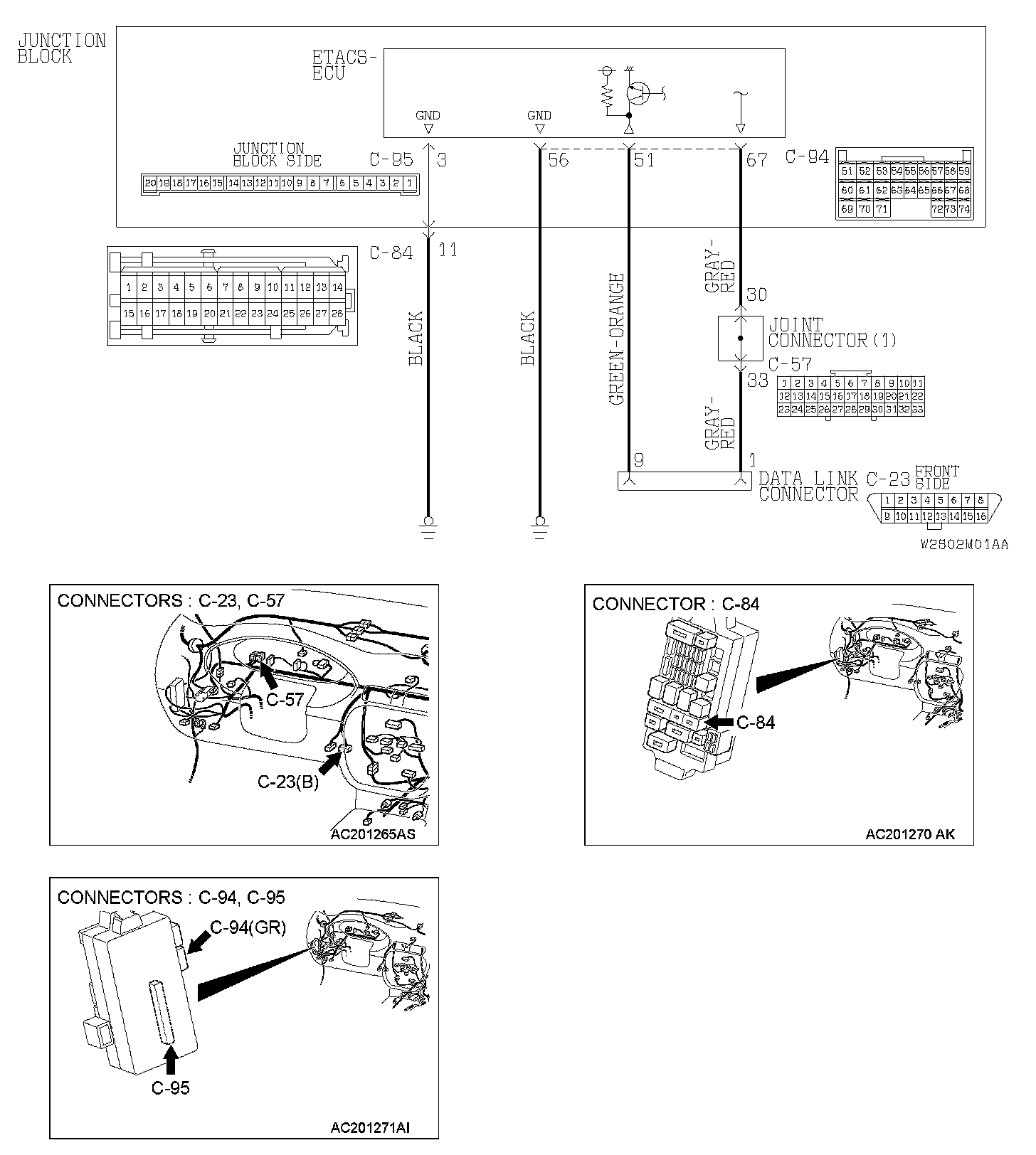
TECHNICAL DESCRIPTION (COMMENT)
The SWS monitor kit may be connected improperly.
TROUBLESHOOTING HINTS
- The SWS monitor body (I/F cartridge) may be defective
- The SWS monitor harness may be defective
- The ETACS-ECU may be defective
- The wiring harness or connectors may have loose corroded or damaged terminals or terminals pushed back in the connector
DIAGNOSIS
Required Special Tools:
- MB991223: Harness Set
- MB991502: Scan Tool (MUT-II)
- MB991862: SWS monitor kit
STEP 1. Verify SWS monitor kit MB991862 for proper connection.
Q: Is SWS monitor kit MB991862 connected with the column switch properly?
YES: Go to Step 2.
NO: Connect SWS monitor kit MB991862 to the column switch securely.
STEP 2. Verify the power supply circuit to the ETACS-ECU.
Q: Does the system communicate with scan tool MB991502 when the ignition switch is turned to the "ON" position?
YES: Refer to Inspection Procedure A-3 "Communication with the ETACS-ECU is not possible."
NO: Go to Step 3.
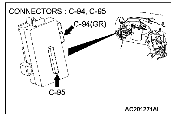
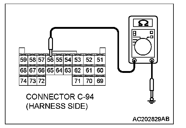
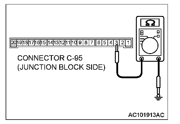
STEP 3. Check the ground circuit to the ETACS-ECU. Test at ETACS-ECU connectors C-94 and C-95.
1. Disconnect ETACS-ECU connectors C-94 and C-95 and measure the resistance available at the junction block side of the connector.
2. Measure the resistance value between ETACS-ECU connector C-94 terminal 56 and ground.
- The resistance should measure 2 ohms or less.
Measure the resistance value between ETACS-ECU connector C-95 terminal 3 and ground.
- The resistance should measure 2 ohms or less.
Q: Is the measured resistance 2 ohms or less?
YES: Go to Step 6.
NO: Go to Step 4.
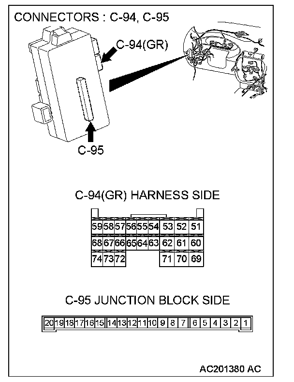
STEP 4. Check ETACS-ECU connectors C-94 and C-95 for loose, corroded or damaged terminals, or terminals pushed back in the connector.
Q: Are ETACS-ECU connectors C-94 and C-95 in good condition?
YES: Go to Step 5.
NO: Repair or replace the damaged component(s). Refer to Harness Connector Inspection. The system should communicate with the SWS monitor normally.
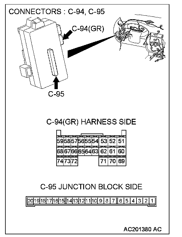
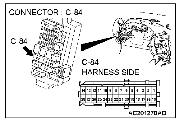
STEP 5. Check the wiring harness between ETACS-ECU connector C-94 (terminal 56) or ETACS-ECU connector C-95 (terminal 3) and the ground.
NOTE: Also check junction block connector C-84 for loose, corroded, or damaged terminals, or terminals pushed back in the connector. If junction block connector C-84 is damaged, repair or replace the damaged components.as described in Harness Connector Inspection.
Q: Is the wiring harness between ETACS-ECU connector C-94 terminal 56.or ETACS-ECU connector C-95 (terminal 3) and the ground in good condition?
YES: No action is necessary and testing is complete.
NO: The wiring harness may be damaged or the connector(s) may have loose corroded or damaged terminals or terminals pushed back in the connector. Repair the wiring harness as necessary. The system should communicate with the SWS monitor kit normally.
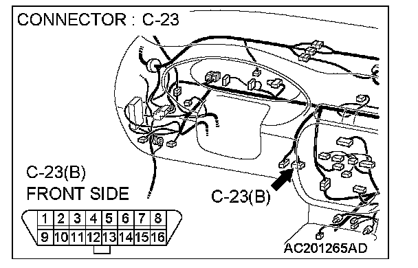
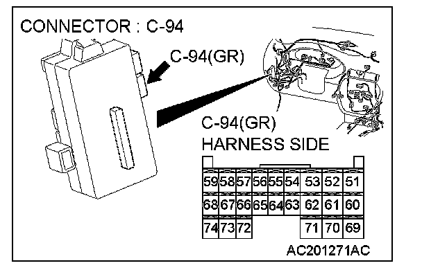
STEP 6. Check ETACS-ECU connector C-94 and data link connector C-23 for loose, corroded or damaged terminals, or terminals pushed back in the connector.
Q: Are ETACS-ECU connector C-94 and data link connector C-23 in good condition?
YES: Go to Step 7.
NO: Repair or replace the damaged component (s). Refer to Harness Connector Inspection. The system should communicate with the SWS monitor kit normally.
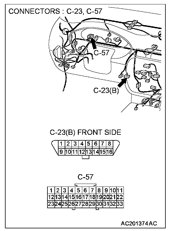
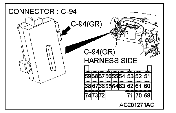
STEP 7. Check the wiring harness between ETACS-ECU connector C-94 (terminal 51 and 67) and data link connector C-23 (terminal 9 and 1).
NOTE: Also check joint connector C-57 for loose, corroded, or damaged terminals, or terminals pushed back in the connector. If joint connector C-57 is damaged, repair or replace the connector as described in Harness Connector Inspection.
Q: Is the wiring harness between ETACS-ECU connector C-94 (terminal 51 and 67) and data link connector C-23 (terminal 9 and 1) in good condition?
YES: Replace the ETACS-ECU. The system should communicate with the SWS monitor kit normally.
NO: The wiring harness may be damaged or the connector(s) may have loose corroded or damaged terminals or terminals pushed back in the connector. Repair the wiring harness as necessary. The system should communicate with the SWS monitor kit normally.