Inspection Procedure 2
Inspection Procedure 2: Defective Power Supply System Of The Ignition SwitchIgnition Switch Power Supply Circuit:
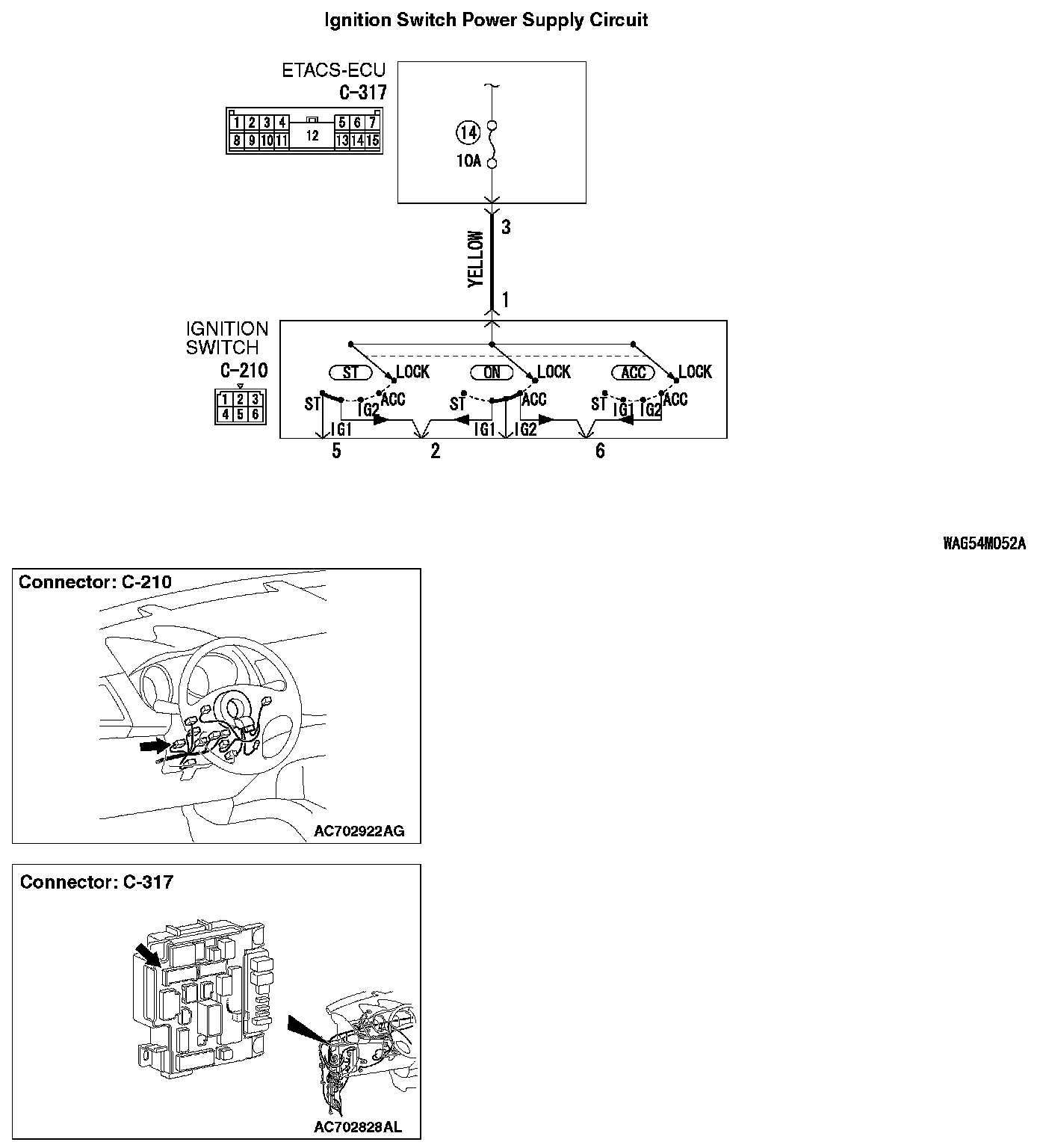
TECHNICAL DESCRIPTION (COMMENT)
When the power supply system of ignition switch has a problem, none of the equipment and system connected to the ignition switch works even if the ignition switch is operated.
TROUBLESHOOTING HINTS
- The ignition switch may be defective
- The fuse No.14 may be defective
- The ETACS-ECU may be defective
- The wiring harness or connectors may have loose, corroded, or damaged terminals, or terminals pushed back in the connector
DIAGNOSIS
Required Special Tools:
- MB992006: Extra fine probe
- MB991223: Harness set
STEP 1.Check ignition switch connector C-210 for loose, corroded or damaged terminals, or terminals pushed back in the connector.
Q: Is ignition switch connector C-210 in good condition?
YES : Go to Step 2.
NO : Repair the defective connector.
STEP 2.Check the battery power supply circuit to the ignition switch. Measure the voltage at ignition switch connector C-210.
1. Disconnect the connector, and measure at the wiring harness side.
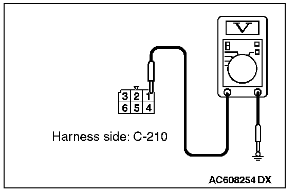
2. Measure the voltage between terminal 1 and ground.
- The voltage should measure approximately 12 volts (battery positive voltage).
Q: Is the measured voltage approximately 12 volts (battery positive voltage)?
YES : Go to Step 6.
NO : Go to Step 3.
STEP 3.Check the fuse No.14.Q: Is the check result normal?
YES : Go to Step 4.
NO : Replace the fuse No.14.(Check that there is not a short to ground in the circuit of lower reaches before replacing. If there are any problems, replace the fuse after the circuit of lower reaches is repaired.)
STEP 4.Check ETACS-ECU connector C-317 for loose, corroded or damaged terminals, or terminals pushed back in the connector.
Q: Is ETACS-ECU connector C-317 in good condition?
YES : Go to Step 5.
NO : Repair the damaged parts.
STEP 5.Check the Wiring harness between ignition switch connector C-210 (terminal No.1) and ETACS-ECU connector C-317 (terminal No.3).
- Check the battery power supply line for open circuit.
Q: Is the check result normal?
YES : Go to Step 7.
NO : Repair the wiring harness.
STEP 6. Check the ignition switch.
Remove the ignition switch. Then check continuity between the switch terminal.
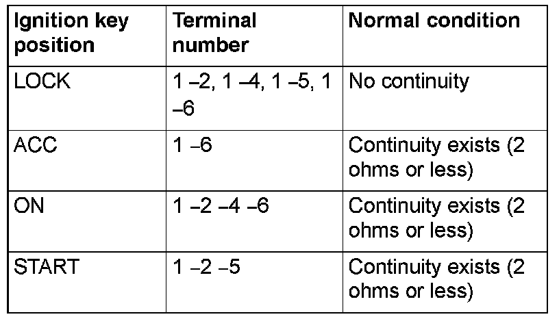
Q: Is the ignition switch in good condition?
YES : Go to Step 7.
NO : Replace the ignition switch.
STEP 7. Retest the system.
Q: When the ignition switch is operated, do the equipment and system work normally?
YES : The trouble can be an intermittent malfunction
NO : Replace the ETACS-ECU.