Rear Wiper System Malfunction
Rear Wiper System Malfunction
Diagnostic Instructions
* Perform the Diagnostic System Check - Vehicle Diagnostic System Check - Vehicle prior to using this diagnostic procedure.
* Review Strategy Based Diagnosis Strategy Based Diagnosis for an overview of the diagnostic approach.
* Diagnostic Procedure Instructions Diagnostic Procedure Instructions provides an overview of each diagnostic category.
Diagnostic Fault Information
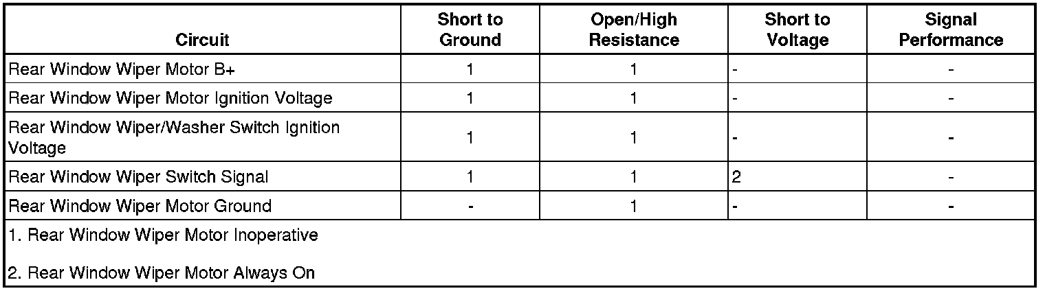
Circuit/System Description
The rear wiper is controlled based on an input from the rear wiper/washer switch. When closed, the wiper ON and wiper DELAY switches provide a unique voltage signal to the rear window wiper motor indicating the desired speed. Each switch has a unique resistor that drops the voltage to a specified value which is interpreted by the rear window wiper motor as ON or DELAY. The rear wiper motor receives B+ voltage from the underhood fuse block and accessory voltage from the body control module (BCM).
Reference Information
Schematic Reference
Wiper/Washer Schematics Electrical Diagrams
Connector End View Reference
Component Connector End Views 1-2 Shift Solenoid (SS) Valve (MN5)
Description and Operation
Wiper/Washer System Description and Operation Description and Operation
Electrical Information Reference
* Circuit Testing Circuit Testing
* Connector Repairs Connector Repairs
* Testing for Intermittent Conditions and Poor Connections Testing for Intermittent Conditions and Poor Connections
* Wiring Repairs Wiring Repairs
Scan Tool Reference
Control Module References Programming and Relearning for scan tool information
Circuit/System Verification
1. Ignition ON, liftgate closed, verify the liftgate ajar indicator is not illuminated.
• If the liftgate ajar indicator is illuminated, refer to Liftgate Ajar Indicator Malfunction Liftgate Ajar Indicator Malfunction
2. Rear wiper switch in the WIPER position. The rear wiper should turn ON.
• If the rear wiper does not turn ON, refer to circuit system testing.
Circuit/System Testing
1. Ignition OFF, disconnect the harness connector at the multifunction switch.
2. Ignition ON, test for ignition voltage between the ignition voltage circuit terminal 11 and ground
• If not the specified value, test the ignition circuit for a short to ground or an open/ high resistance. If the circuit tests normal, replace the BCM.
3. Ignition OFF, connect the harness connector at the multifunction switch. Disconnect the harness connector at the rear window wiper/washer module.
4. Test for less than 10 ohms between the ground circuit terminal 4 and ground.
• If greater than the specified range, test the ground circuit for an open/high resistance.
5. Ignition ON, verify a test lamp illuminates between the B+ circuit terminal 5 and ground.
• If the test lamp does not illuminate, test the B+ circuit for a short to ground or an open/high resistance.
6. Ignition ON, rear wiper/washer switch in the WIPER position, test for ignition voltage between the signal circuit terminal 1 and ground.
• If not the specified value, test the signal circuit for a short to ground or an open/high resistance, If the circuit tests normal, replace the multifunction switch.
7. Liftgate closed, test for infinite resistance between the signal circuit terminal 3 and ground.
• If not the specified value, test the signal circuit for a short to ground.
8. If all circuits test normal, test or replace the rear window wiper/washer module.
Repair Instructions
Perform the Diagnostic Repair Verification Verification Tests after completing the diagnostic procedure.
* Windshield Wiper and Washer Switch Replacement Service and Repair
* Liftgate Wiper Motor Replacement Liftgate Wiper Motor Replacement
* Rear Window Washer Pump Replacement Rear Window Washer Pump Replacement