Track Control Arm, Ball Joint, Guide Link and Level Control System Sensor Overview
Track Control Arm, Ball Joint, Guide Link and Level Control System Sensor Overview
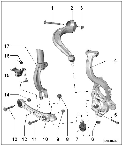
1 Bolt
• Always replace if removed.
2 Guide Link
• Removing and installing, refer to => [ Guide Link ] Front Suspension.
• Bonded rubber bushing, removing and installing, guide link, refer to => [ Guide Link Bonded Rubber Bushing ] Guide Link Bonded Rubber Bushing.
3 Nut
• 70 Nm + 180° turn
• Always replace if removed.
• Must be tightened in the control position. Refer to => [ Wheel Bearing, with Air Suspension, Lifting to Curb Weight Position ] Wheel Bearing, With Air Suspension, Lifting to Curb Weight Position or => [ Wheel Bearing, with Coil Spring, Lifting to Curb Weight Position ] Wheel Bearing, With Coil Spring, Lifting to Curb Weight Position.
4 Wheel Bearing Housing
5 Bolt
• 40 Nm
• Always replace if removed.
6 Nut
• 140 Nm
• Always replace if removed.
• After loosening threaded connection of guide control arm to wheel bearing housing, adhesive residue must be removed on thread of linkage stub.
7 Ball Joint
• Removing and installing, refer to => [ Ball Joint ] Service and Repair.
• Different versions. Allocation, refer to the Parts Catalog.
• Note installation position => [ Installing ] Service and Repair.
• Install the ball joint into the wheel bearing housing as far as the contact surface.
8 Nut
• M12: 120 Nm
• M14: 140 Nm
• Different versions. Allocation, refer to the Parts Catalog.
• Always replace if removed.
• After loosening threaded connection on the ball joint to the wheel bearing housing, adhesive residue must be removed on thread of linkage stub.
9 Nut
• 90 Nm + 90° turn
• Always replace if removed.
• Must be tightened in the control position, refer to => [ Wheel Bearing, with Air Suspension, Lifting to Curb Weight Position ] Wheel Bearing, With Air Suspension, Lifting to Curb Weight Position or => [ Wheel Bearing, with Coil Spring, Lifting to Curb Weight Position ] Wheel Bearing, With Coil Spring, Lifting to Curb Weight Position.
10 Track Control Arm
• Removing and installing, refer to => [ Track Control Arm ] Track Control Arm.
• Different versions. Allocation, refer to the Parts Catalog.
• Bonded rubber bushing, control arm, wheel bearing housing side, removing and installing, refer to => [ Track Control Arm Bonded Rubber Bushing, Wheel Bearing Housing Side ] Track Control Arm Bonded Rubber Bushing, Wheel Bearing Housing Side.
• Bonded rubber bushing, removing and installing, control arm, subframe side, refer to => [ Track Control Arm Bonded Rubber Bushing, Subframe Side ] Track Control Arm Bonded Rubber Bushing, Subframe Side.
11 Bolt
• Always replace if removed.
12 Nut
• 9 Nm
13 Bolt
• Always replace if removed.
14 Nut
• 70 Nm + 180° turn
• Always replace if removed.
• Must be tightened in the control position. Refer to => [ Wheel Bearing, with Air Suspension, Lifting to Curb Weight Position ] Wheel Bearing, With Air Suspension, Lifting to Curb Weight Position or => [ Wheel Bearing, with Coil Spring, Lifting to Curb Weight Position ] Wheel Bearing, With Coil Spring, Lifting to Curb Weight Position.
15 Left Front Level Control System Sensor (G78) or Right Front Level Control Sensor (G289)
• Only remove and install or replace completely. Refer to => [ Front Vehicle Level Sensor ] Front Vehicle Level Sensor.
• The sensor lever must point toward the back.
• Adjust the headlamp after loosening.
• If the vehicle level sensor was removed and installed or if the linkage was loosened, the control position must be programmed again using vehicle diagnosis tester.
• If the control position was reprogrammed on vehicles with lane assist, the camera control module must be calibrated again. Refer to => [ Camera Control Module (J852), Lane Assist, Calibrating ] Testing and Inspection.
16 Bolt
• 9 Nm
17 Shock Absorber Fork