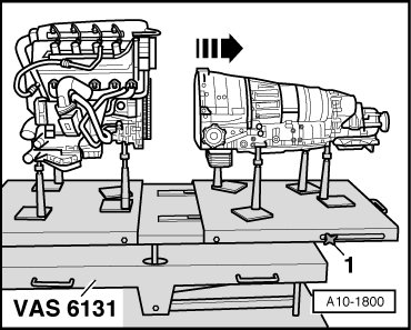
Engine and Multitronic Transmission, Separating
Engine and Multitronic Transmission, Separating
Special tools, testers and auxiliary items required
• Support Set (VAS 6131/10) and Supplementary Set Audi A6 (C6) (VAS 6131/12)
Procedure
• Engine/transmission assembly removed and placed on Scissor Lift Table (VAS 6131 A).
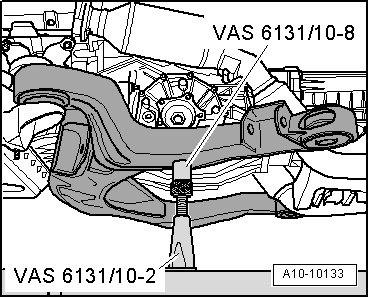
- Rotate the left and right mounting element spindles on the subframe all the way down.
- Remove the mounting pins from the spindles.
• A second technician is required to remove subframe.
- Remove the subframe to the side.
- Remove the base plates on the subframe support elements from the (VAS 6131 A).
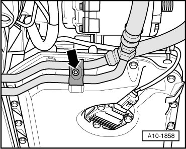
- Remove the ATF pipe bracket - arrow -.
• Follow the rules for clean working conditions when working on the multitronic transmission.
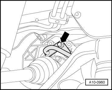
- Remove bolt - arrow - and disconnect ATF lines from transmission.
- Seal the open lines and connections with clean plugs from the (VAS 6122).
• The support points for front of engine and tunnel cross member remain unchanged.
- Set up (VAS 6131 A) with the (VAS 6131/10) and (VAS 6131/12) as follows:
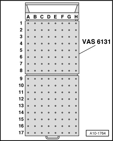
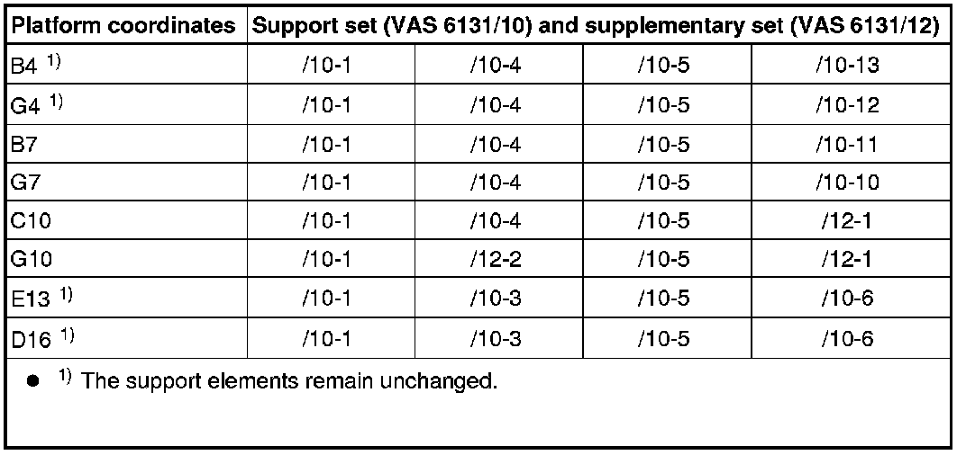
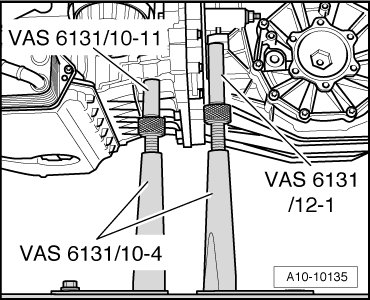
- Attach the mounting elements from the (VAS 6131/10) and (VAS 6131/12) to the left side of the engine/transmission subassembly as illustrated.
- Attach the mounting elements from the (VAS 6131/10) and (VAS 6131/12) to the right of the engine/transmission assembly as illustrated.
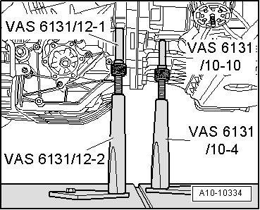
- Rotate mounting element spindles upward until all mounting pins come in contact with mounting points.
- Attach mounting element base plates to (VAS 6131 A) and tighten to 20 Nm.
CAUTION!
Risk of destroying transmission control module (Mechatronic) with static discharge.
• Do not touch contacts in transmission connector with hands.
- Release electrical connector - 1 - and remove from transmission.
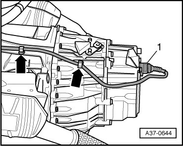
- Free up the wiring harness to the engine - arrows -.
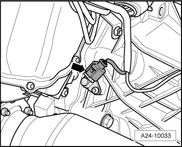
- Disconnect electrical connector - arrow - for Engine Speed (RPM) Sensor (G28).
- Disconnect the electrical connector - 2 - for the Oxygen Sensor (O2S) 2 Behind Three Way Catalytic Converter (TWC) (G131) and free up the electrical wire.
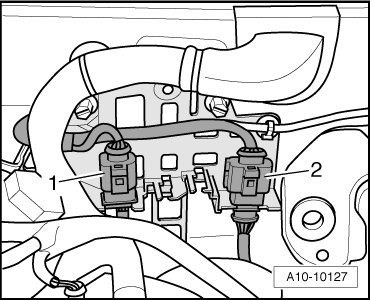
• In the illustration, the electrical connector is installed.
• Ignore - 1 -.
CAUTION!
Danger of damaging the decoupling element.
• Decoupling element must not be bent more than 10°.
• Do not load decoupling element on cable.
• Do not damage wire mesh at decoupling element.
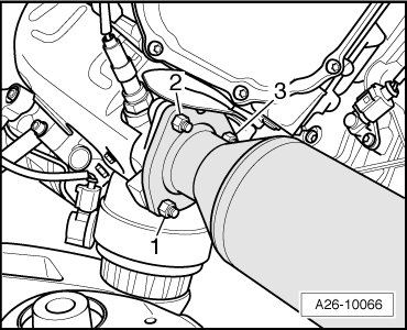
- Remove the bolts - 1 - on the rear bracket for the exhaust system.
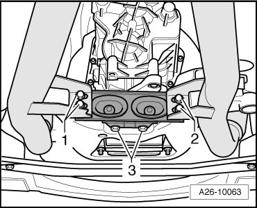
• Ignore - 2 and 3 -.
- Remove the nuts - 1, 2 and 3 - and then remove the left front exhaust pipe with the catalytic converter.
- Disconnect the electrical connector - 2 - for the Oxygen Sensor (O2S) Behind Three Way Catalytic Converter (TWC) (G130) and free up the electrical wire.
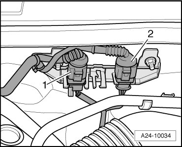
• In the illustration, the electrical connector is installed.
• Ignore - 1 -.
CAUTION!
Danger of damaging the decoupling element.
• Decoupling element must not be bent more than 10°.
• Do not load decoupling element on cable.
• Do not damage wire mesh at decoupling element.
- Remove the bolts - 2 - on the rear bracket for the exhaust system.
• Ignore - 1 and 3 -.
- Remove the bolt - 1 - on the right catalytic converter bracket.
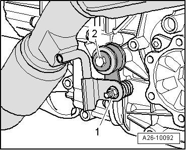
• Ignore - 2 -.
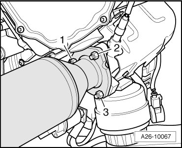
- Remove the nuts - 1, 2 and 3 - and then remove the right front exhaust pipe with the catalytic converter.
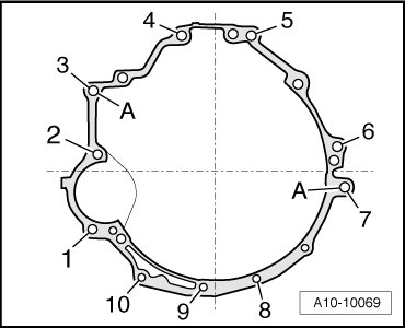
- Remove the bolts - 1 to 10 - for the transmission/engine connection.
- Loosen clamping bolts - 1 - on sides of (VAS 6131 A) and pull rear table plate with transmission toward rear - arrow -.