Computers and Control Systems: Locations
Component Location Overview
Engine Compartment, Left
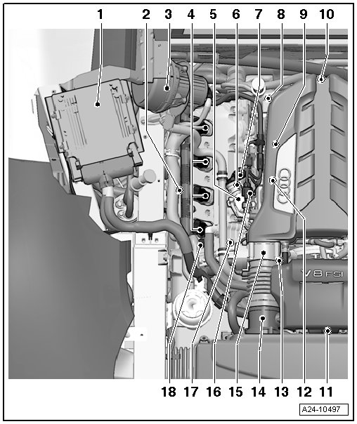
1 Engine Control Module 2 (J624)
• Component location
• Removing and installing, refer to => [ Engine Control Module 2 ] Engine Control Module 2
2 Camshaft Position Sensor 4 (G301)
• Component location
• Removing and installing, refer to => [ Camshaft Position Sensor ] Service and Repair
• 10 Nm
3 Secondary Air Injection Pump Motor (V101)
• Secondary air injection pump relay (J299)
4 Ignition Coils, Cylinder Bank 2
• Ignition coil 5 with power output stage (N323)
• Ignition coil 6 with power output stage (N324)
• Ignition coil 7 with power output stage (N325)
• Ignition coil 8 with power output stage (N326)
• Component location
5 High Pressure Pump Cylinder Bank 2
• Removing and installing, refer to => [ High Pressure Pumps ] High Pressure Pumps
6 Camshaft Position Sensor 2 (G163)
• Component location
• Removing and installing, refer to => [ Camshaft Position Sensor ] Service and Repair
• 10 Nm
7 Fuel Metering Valve 2 (N402)
• Component location
8 Electrical Connectors on Knock Sensor 3 (G198) and Knock Sensor 4 (G199)
• Component location
9 Knock Sensor 3 (G198)
• Component location
• Connector location
• Removing and installing, refer to => [ Knock Sensors ] Service and Repair
• 20 Nm
10 Engine Viewed From Front
• Component location
• Adapt the intake manifold runner position sensor (G336) in the guided functions operating mode under adapting intake manifold runner position sensor after replacing it.
• Intake manifold runner control valve (N316)
• Oil pressure switch (F1)
• Knock sensor 1 (G61) connector
• Knock sensor 2 (G66) connector
• Knock sensor 3 (G198) connector
• Knock sensor 4 (G199) connector
11 Oxygen Sensor Connectors
• Component location
12 Knock Sensor 4 (G199)
• Component location
• Connector location
• Removing and installing, refer to => [ Knock Sensors ] Service and Repair
• 20 Nm
13 Intake Manifold Runner Position Sensor 2 (G512)
• After replacement, adapt in guided functions operating mode in adapting intake manifold runner position sensor
• installed on the rear of the intake manifold
14 Mass Airflow Sensor 2 (G246)
• Component location
• Removing and installing, refer to => [ Mass Air Flow Sensor and Mass Air Flow Sensor 2 ] Service and Repair
15 Throttle Valve Control Module 2 (J544)
• Adapt the throttle valve control module 2 (J544) in the guided functions operating mode after replacing.
• 9 Nm
• Component location
16 Low Fuel Pressure Sensor (G410)
• 15 Nm
• Component location
17 Camshaft Adjustment Valve 2 (N208)
• Component location
18 Exhaust Camshaft Adjustment Valve 2 (N319)
• Component location
Engine Compartment, Right
Components A through L are not shown in the exploded view illustration.
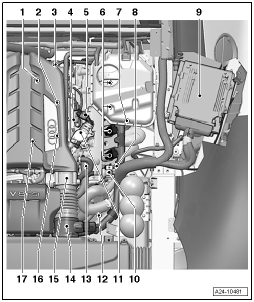
1 - Fuel Pressure Sensor (G247)
• Component location
• Removing and installing, refer to => [ Fuel Pressure Sensor ] Service and Repair
• 22 Nm
2 - Knock Sensor 1 (G61)
• Component location
• Connector location
• Removing and installing, refer to => [ Knock Sensors ] Service and Repair
• 20 Nm
3 - Electrical Connectors on Knock Sensor 1 (G61) and Knock Sensor 2 (G66)
• Connector location
4 - Camshaft Position Sensor (G40)
• Component location
• Removing and installing, refer to => [ Camshaft Position Sensor ] Service and Repair
• 10 Nm
5 - Fuel Metering Valve (N290)
6 - Ignition Coils, Cylinder Bank 1
• Ignition coil 1 with power output stage (N70)
• Ignition coil 2 with power output stage (N127)
• Ignition coil 3 with power output stage (N291)
• Ignition coil 4 with power output stage (N292)
• Component location
7 - Camshaft Position Sensor 3 (G300)
• Component location
• Removing and installing, refer to => [ Camshaft Position Sensor ] Service and Repair
• 10 Nm
8 - Exhaust Camshaft Adjustment Valve 1 (N318)
• Component location
9 - Engine Control Module (J623)
• Component location
• Removing and installing, refer to => [ Engine Control Module ] Engine Control Module
10 - EVAP Canister Purge Regulator Valve 1 (N80)
• Component location
11 - High Pressure Pump
• With fuel metering valve (N290)
• Component location
• Removing and installing, refer to => [ High Pressure Pumps ] High Pressure Pumps
12 - Engine Coolant Temperature Sensor (G62)
• Component location
13 - Camshaft Adjustment Valve 1 (N205)
• Component location
14 - Mass Airflow Sensor (G70)/Intake Air Temperature Sensor (G42)
• Component location
• Removing and installing, refer to => [ Mass Air Flow Sensor and Mass Air Flow Sensor 2 ] Service and Repair
15 - Throttle Valve Control Module (J338)
• Adapt the throttle valve control module (J338) in the guided functions operating mode after replacing.
• 9 Nm
• Component location
16 - Knock Sensor 2 (G66)
• Component location
• Connector location
• Removing and installing, refer to => [ Knock Sensors ] Service and Repair
• 20 Nm
17 - Secondary Air Injection Solenoid Valve (N112)
• Component location
• Installed location
A - Fuel Injectors, Cylinder Bank 1
• Cylinder 1 fuel injector (N30)
• Cylinder 2 fuel injector (N31)
• Cylinder 3 fuel injector (N32)
• Cylinder 4 fuel injector (N33)
• Component location
• Removing and installing, refer to => [ Fuel Injectors ] Fuel Injectors
B - Fuel Injectors, Cylinder Bank 2
• Cylinder 5 fuel injector (N83)
• Cylinder 6 fuel injector (N84)
• Cylinder 7 fuel injector (N85)
• Cylinder 8 fuel injector (N86)
• Component location
• Removing and installing, refer to => [ Fuel Injectors ] Fuel Injectors
C - Engine Speed Sensor (G28)
• Component location
• Removing and installing, refer to => [ Engine Speed Sensor ] Service and Repair
• 9 Nm
D - Heated Oxygen Sensor (G39) (before catalytic converter)
• Component location
• Connector location
• Removing and installing, refer to => [ Oxygen Sensors ] Oxygen Sensors
E - Heated Oxygen Sensor 2 (G108) (in front of catalytic converter)
• Component location
• Connector location
• Removing and installing, refer to => [ Oxygen Sensors ] Oxygen Sensors
F - Oxygen Sensor after Three Way Catalytic Converter (G130)
• Component location
• Connector location
• Removing and installing, refer to => [ Oxygen Sensors ] Oxygen Sensors
G - Oxygen Sensor 2 after Catalytic Converter (G131)
• Component location
• Connector location
• Removing and installing, refer to => [ Oxygen Sensors ] Oxygen Sensors
H - 9-Pin Relay and Fuse Carrier Under the Rear Shelf (on the right side)
• Motronic engine control module power supply relay (J271)
• Auxiliary engine coolant pump relay (J496)
• Starter relay (J53)
• Starter relay 2 (J695)
• Secondary air injection pump relay (J299)
• Engine component power supply relay (J757)
• Locations
I - Accelerator Pedal Position Sensor (G79)/Accelerator Pedal Position Sensor 2 (G185)
J - Brake Light Switch (F)/Brake Pedal Switch (F47)
K - Clutch Pedal Starter Interlock Switch (F194) and Clutch Pedal Switch (F36)
• Only for vehicles with manual transmission
L - Clutch Position Sensor (G476)
Location Engine Control Module (J623)
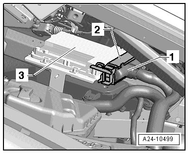
1 Connector
2 Safety bar
3 Engine control module (J623)
• under the right engine compartment trim
• Engine control module (J623), removing and installing => [ Engine Control Module ] Engine Control Module
Location Engine Control Module 2 (J624)
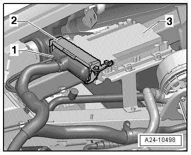
1 Connector
2 Safety bar
3 Engine control module 2 (J624)
• under the left engine compartment trim
• Engine control module 2 (J624), removing and installing, refer to => [ Engine Control Module 2 ] Engine Control Module 2
Engine Speed Sensor (G28)
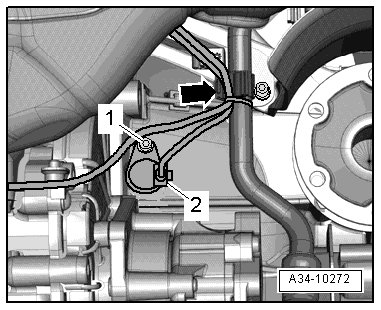
Removing and installing, refer to => [ Engine Speed Sensor ] Service and Repair
Component Locations in the 9-Pin Relay and Fuse Carrier under the Rear Shelf (on the right side)
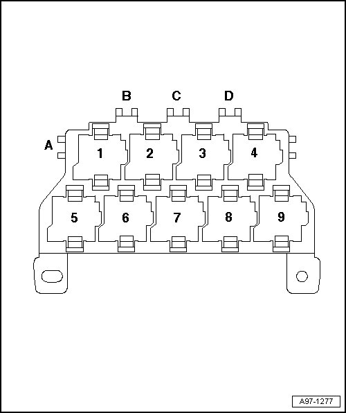
1 Motronic engine control module power supply relay (J271)
2 Auxiliary engine coolant pump relay (J496)
3 Starter relay (J53)
4 Starter relay 2 (J695)
5 Secondary air injection pump relay (J299)
6 Engine component power supply relay (J757)
Intake Manifold Runner Position Sensor 2 (G512) - 2 -
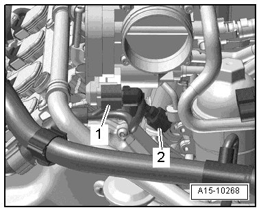
1 Throttle valve control module 2 (J544)
• Installed on the rear of the intake manifold.
• The throttle valve control module 2 (J544) must be removed to remove and install the intake manifold runner position sensor 2 (G512) - 2 -.
Throttle Valves and Mass Airflow Sensor
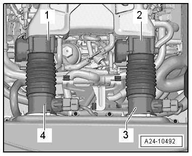
1 Throttle valve control module 2 (J544)
2 Throttle valve control module (J338)
3 Mass airflow sensor (G70) and intake air temperature sensor (G42)
4 Mass airflow sensor 2 (G246)
High Pressure Pump, Cylinder Bank 1 - 2 -
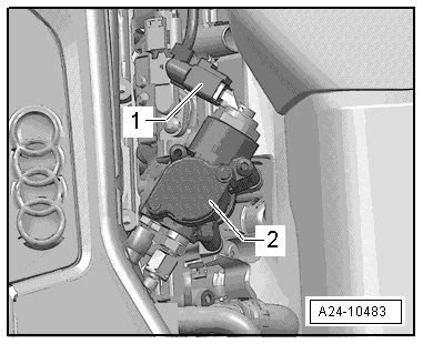
1 Fuel metering valve (N290)
High Pressure Pump, Cylinder Bank 2 - 3 -
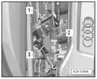
1 Fuel metering valve 2 (N402)
2 Low fuel pressure sensor (G410)
Engine Coolant Temperature Sensor (G62) - 1 -
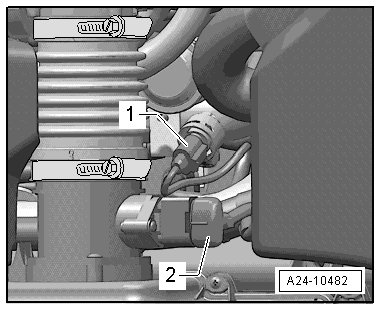
2 Mass airflow sensor (G70)
EVAP Canister Purge Regulator Valve 1 (N80) - 1 -
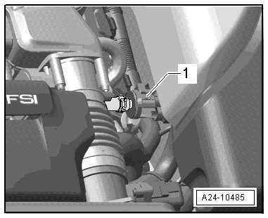
Component Locations on Cylinder Bank 1
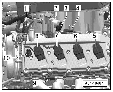
1 Camshaft adjustment valve 1 (N205)
2 High pressure pump cylinder bank 1
3 Fuel metering valve (N290)
4 Camshaft position sensor (G40)
5 Ignition coil 1 with power output stage (N70)
6 Ignition coil 2 with power output stage (N127)
7 Ignition coil 3 with power output stage (N291)
8 Ignition coil 4 with power output stage (N292)
9 Camshaft position sensor 3 (G300), removing and installing, refer to => [ Camshaft Position Sensor ] Service and Repair
10 Exhaust camshaft adjustment valve 1 (N318)
• The throttle valve control module (J338) must be removed to remove and install the camshaft adjustment valve 1 (N205).
Component Locations on Cylinder Bank 2
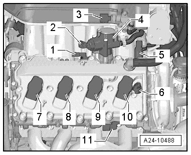
1 Camshaft position sensor 2 (G163)
2 Fuel metering valve 2 (N402)
3 Low fuel pressure sensor (G410)
4 High pressure pump cylinder bank 2
5 Camshaft adjustment valve 2 (N208)
6 Exhaust camshaft adjustment valve 2 (N319)
7 Ignition coil 5 with power output stage (N323)
8 Ignition coil 6 with power output stage (N324)
9 Ignition coil 7 with power output stage (N325)
10 Ignition coil 8 with power output stage (N326)
11 Camshaft position sensor 4 (G301), removing and installing, refer to => [ Camshaft Position Sensor ] Service and Repair
• The throttle valve control module 2 (J544) must be removed to remove and install the camshaft adjustment valve 2 (N208).
Component Locations, Inside of Cylinder Bank 1
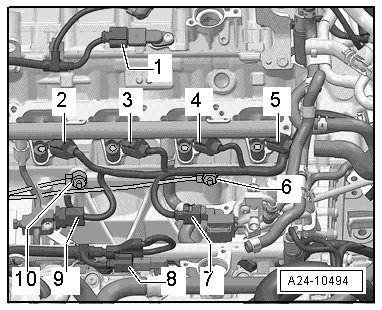
• Under intake manifold
1 Camshaft position sensor (G40)
2 Cylinder 1 fuel injector (N30)
3 Cylinder 2 fuel injector (N31)
4 Cylinder 3 fuel injector (N32)
5 Cylinder 4 fuel injector (N33)
6 Knock sensor 2 (G66)
7 Secondary air injection solenoid valve (N112))
8 Camshaft position sensor 2 (G163)
9 Fuel pressure sensor (G247)
10 Knock sensor 1 (G61)
Installed Location of the Secondary Air Injection Solenoid Valve
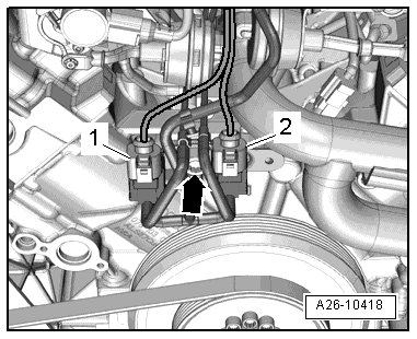
1. Secondary air injection solenoid valve (N112)
2. Secondary air injection solenoid valve 2 (N320)
• Installed location: under the intake manifold.
Component Locations, Inside of Cylinder Bank 2
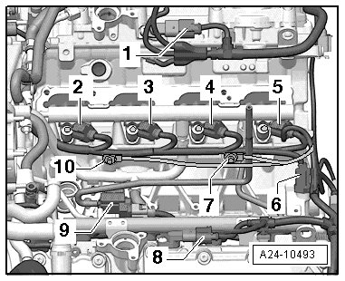
• Under intake manifold
1 Camshaft position sensor 2 (G163)
2 Cylinder 8 Fuel Injector (N86)
3 Cylinder 7 Fuel Injector (N85)
4 Cylinder 6 fuel injector (N84)
5 Cylinder 5 fuel injector (N83)
6 Oil pressure switch (F1)
7 Knock sensor 3 (G198)
8 Camshaft position sensor (G40)
9 Secondary air injection solenoid valve (N112))
10 Knock sensor 4 (G199)
Component Locations, Engine from Front
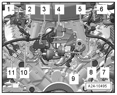
1 High pressure pump cylinder bank 1 with fuel metering valve (N290)
2 Camshaft position sensor (G40)
3 Intake manifold runner position sensor (G336)
4 Intake manifold runner control valve (N316)
5 Camshaft position sensor 2 (G163)
6 High pressure pump cylinder bank 2 with fuel metering valve 2 (N402)
7 Knock sensor 4 (G199) connector
8 Knock sensor 3 (G198) connector
9 Oil pressure switch (F1)
10 Knock sensor 2 (G66) connector
11 Knock sensor 1 (G61) connector
Oxygen Sensor Connector Bracket
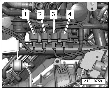
1. Oxygen sensor 2 after catalytic converter (G131)
2. Heated oxygen sensor 2 (G108) (in front of catalytic converter)
3. Heated oxygen sensor (G39)(before catalytic converter)
4. Oxygen sensor after three way catalytic converter (G130)
Component Location, Oxygen Sensors, Cylinder Bank 1
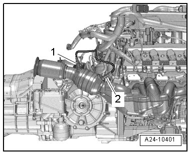
1. Oxygen sensor after three way catalytic converter (G130)
2. Heated oxygen sensor (G39)(before catalytic converter)
Removing and installing, refer to => [ Oxygen Sensors ] Oxygen Sensors
Component Location, Oxygen Sensors, Cylinder Bank 2
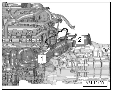
1. Heated oxygen sensor 2 (G108) (in front of catalytic converter)
2. Oxygen sensor 2 after catalytic converter (G131)
Removing and installing, refer to => [ Oxygen Sensors ] Oxygen Sensors