Secondary Air Injection Left Combination Valve
Secondary Air Injection Left Combination Valve
Special tools, testers and auxiliary items required
• Hose clamps up to 25 mm diameter (3094)
Removing
• All cable ties opened or cut during engine removal must be reinstalled at the same locations during installation.
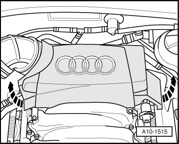
- Remove rear engine cover - arrows -.
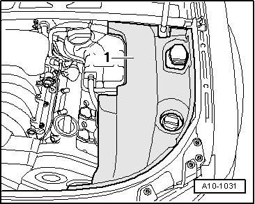
- Remove cover - 1 - in engine compartment (left side).
- Clamp off coolant hose - 2 - using hose clamp (3094) and disconnect from coolant expansion tank.
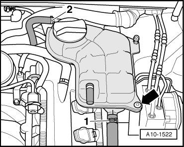
- Seal connection using a plug that fits.
- Remove coolant expansion tank - arrow -.
- Disconnect electrical wire to Engine Coolant Level (ECL) Warning Switch (F66) at bottom on expansion tank and set aside coolant expansion tank with coolant hose - 1 - connected.
- Remove electrical harness connectors - 1 to 4 - from bracket at left of bulkhead.
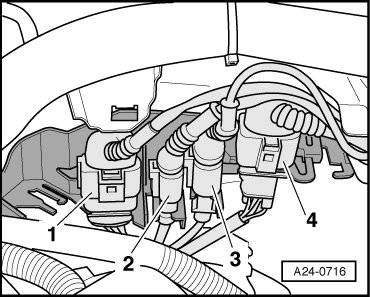
- Remove bracket from bulkhead.
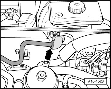
- Disconnect vacuum line - arrow - to brake booster at bulkhead.
- Disconnect electrical harness connector - arrow - for Camshaft Position (CMP) Sensor 2 (G163) on left cylinder head.
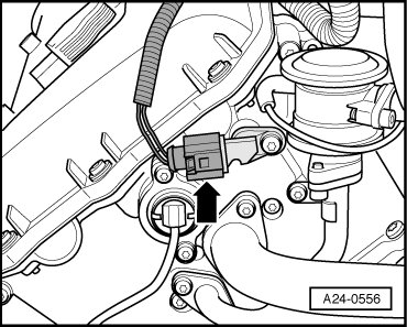
• Illustration depicts engine from rear.
- Disconnect vacuum hose - 3 -.
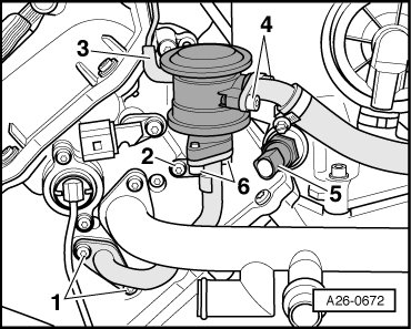
- Remove bolts - 4 -.
- Disconnect electrical harness connector from Oil Pressure Switch (F1) - 5 -.
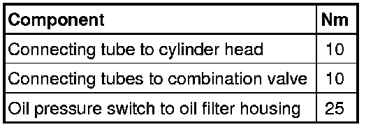
- Remove oil pressure switch.
- Remove bolts - 1 - and - 2 -.
- Swing combination valve and remove bolts - 6 -.
- Remove combination valve and connecting tube.
• Illustration depicts engine from rear.
Installing
Installation is in reverse order of removal, note the following:
• Always replace gaskets and seals.
• Note installation position of seal between cylinder head and connecting tube.
• Secure all hose connections using hose clamps appropriate for the model type.
• During installation, all cable ties must be re-installed at the same location.
- Check coolant level => [ Check coolant level. ] Procedures.
Tightening Specifications