Chain and Disc Set I
Chain and Disc Set I
Special tools, testers and auxiliary items required
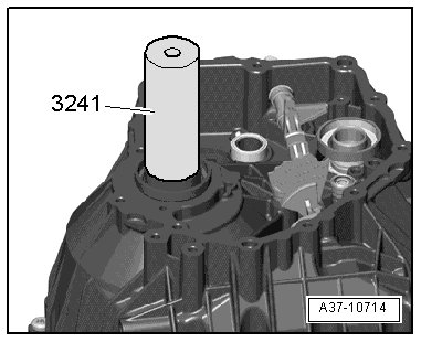
• Seal installer (3241)
• Puller (T10055)
• Pre-tensioning tool (T40130)
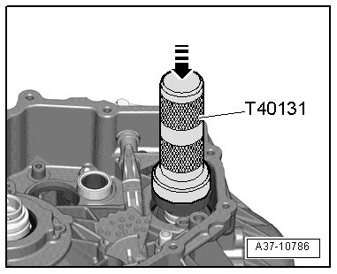
• Thrust piece (T40131)
• Puller (T40132)
• Pressure air hose for tire valves
Removing
Proceed as follows:
- Remove transmission.
- Attach transmission to assembly stand => [ Transmission, Securing to Engine and Transmission Holder ] Transmission, Securing to Engine and Transmission Holder.
- Remove transmission.
- Remove Transmission control unit (TCU) (J217) => [ Transmission Control Module ] Service and Repair.
- Remove hydraulic control unit => [ Hydraulic Control Module ] Service and Repair.
- Remove axial sealing elements - A - (4 pieces) and - B -.
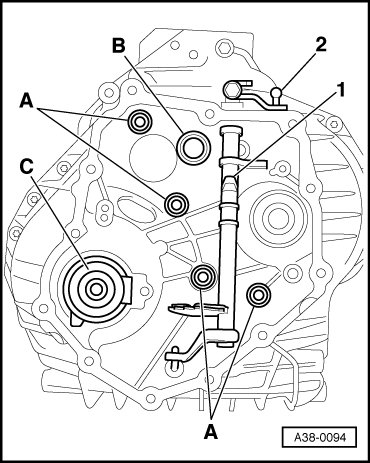
• The axial sealing elements must be replaced.
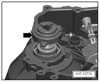
- Remove cover- arrow - from sensor wheel "II ".
- Remove sensor wheel "II" using 2 screwdrivers - arrows -.
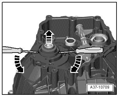
• The sensor wheel must be replaced.
- Remove sensor wheel using "I" with puller ( T40132) and puller (T10055).
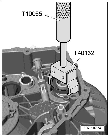
• The sensor wheel must be replaced.
- Remove oil pipe - arrow - by hand upward.
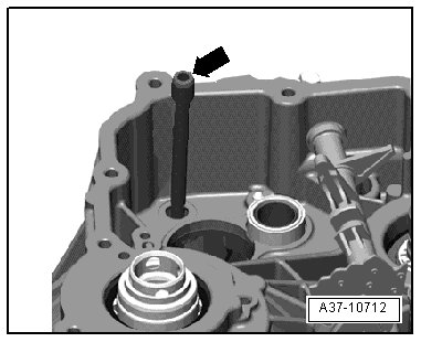
• Do not use any tools otherwise the sealing surfaces will be damaged.
- Remove circlip - 3 - from disc set shaft " I" - 1 -.
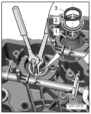
- Mark and remove shim - 2 -.
CAUTION!
Danger of interchanging.
• Be careful not to interchange the thrust washer => [ (Item 13) Thrust washer ] Chain and Disc Set I Assembly Overview with the shim - 2 - under the circlip - 3 -.
• To prevent interchanging them, secure the shim - 2 - to circlip - 3 - with a tie wrap.
- Remove intermediate housing - arrow -; pay attention to the different length; if necessary, mark the installation position of the bolts.
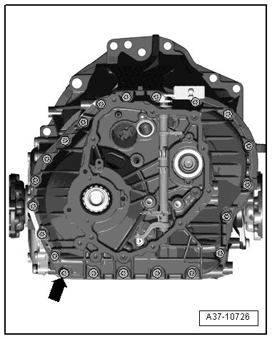
- Remove intermediate housing.
- Mark thrush washer - 1 - and remove it from the disc set "I" - 3 -.
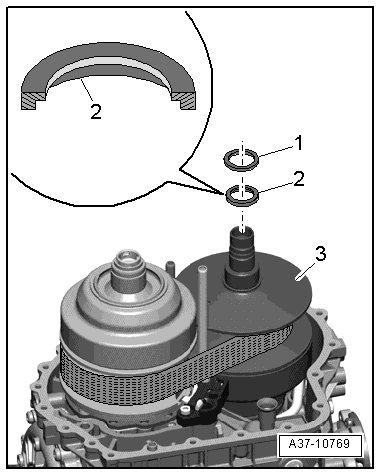
- Remove spacer ring - 2 - (if equipped depending on version!) from disc set "I".
CAUTION!
Danger of interchanging.
• Be sure not to interchange the thrust washer - 1 - with the shim => [ (Item 12) Adjustment shim ] Chain and Disc Set I Assembly Overview under the circlip.
• Mark the thrust washer - 1 - with color.
- Remove intermediate housing seal - 1 -.
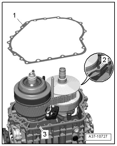
- Remove alignment bushing - 3 -.
• The alignment bushing - 3 - must be removed, so that the retaining device (T40130/1) can be mounted to the transmission.
• The alignment bushing - 2 - can remain attached to the transmission.
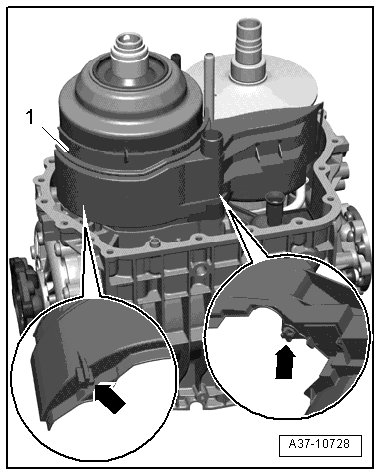
- Remove oil guide piece "I" - 1 -; to do so, carefully remove the retaining pins - arrows -.
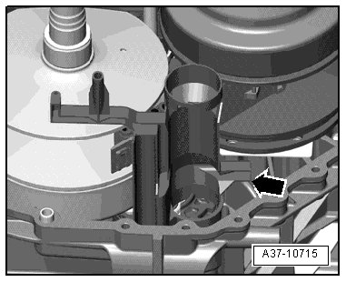
- Pull oil guide piece "II" - arrow - upward.
Measure chain height:
• For the chain height, the height of the chain bolt is used.
- Measure height - a - of the chain bolt - 1 -.
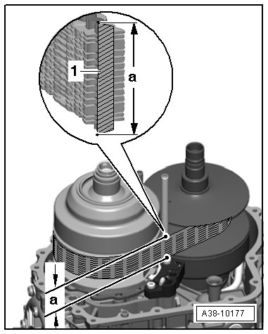
• The chain and the chain bolt - 1 - are illustrated in section.
• In the following work procedure, there will be a difference between two chain heights.
Transmission with chain height - a - = 34 mm:
- Mount retaining device (T40130/2) onto disc set " II".
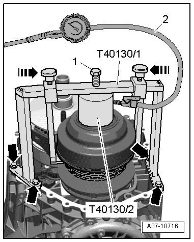
• The O-ring in retaining device (T40130/2) and sealing surfaces on the disc set must be clean and coated with ATF.
- Center aligning device (T40130/1) to the adapter (T40130/2) and bolt is to the transmission housing- lower arrows -, as illustrated.
- Insert bolt - 1 - far enough until the adapter (T40130/2) presses against the disc set "II".
- Connect pressure air hose - 2 - for the tire valves to the adapter (T40130/2) and give approximately 3 bar pressure.
• The disc set opens, the chain relaxes.
- To secure the upper sides, push both hooks in direction of - arrow -.
- Lock hooks in this position with the knurled screws, at the same time, do not clamp the chain.
Transmission with chain height - a - = 38 mm:
- Mount retaining device (T40130/2) onto the disc set "II".
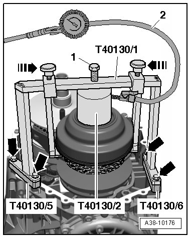
• The O-ring in the retaining device (T40130/2) and sealing surfaces on the disc set must be clean and coated with ATF.
- Center frame (T40130/1) with spacers (T40130/5) and (T40130/6) on the retaining device (T40130/2) and mount it to the transmission housing - lower arrows -, as illustrated.
- Insert bolt - 1 - far enough until adapter (T40130/2) presses against the disc set "II".
- Connect pressure air hose - 2 - for the tire valves to adapter (T40130/2) and give approximately 3 bar pressure.
• The disc set opens, the chain relaxes.
- To secure the upper sides, push both hooks in direction of - arrow -.
- Lock hooks in this position with the knurled screws, at the same time, do not clamp the chain.
Continuation for transmission with all chain heights:
- Turn chain so that the link with the production date stamped on it - A - is visible.
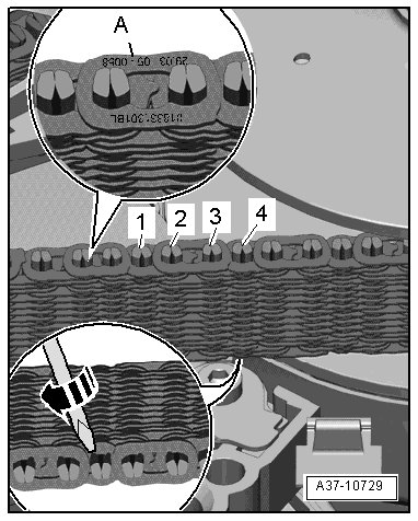
- Open chain on the 4th chain bolt next to the marked chain link.
- Place a rag under chain to prevent any welding points from falling into the transmission.
- Break off any lower welding points on both halves of the 4th chain bolt - arrow -.
- Remove two piece chain bolt upward.
CAUTION!
Do not bend the chain, this could damage it.
- Mark installation position of the glide track - 2 -.
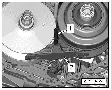
- Unclip glide track on the oil pipe - 1 -, remove the chain and glide track.
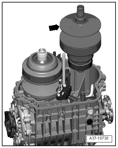
- Remove disc set "I" - arrow - upward.
Installing
• Tightening specifications => [ Chain and Disc Set I Assembly Overview ] Chain and Disc Set I Assembly Overview.
CAUTION!
• Check bearing "D" and bearing "E" for wear => [ Bearings D, E and G, Checking for Wear ] [1][2]Bearings D, E and G, Checking for Wear.
• Check chain, disc set "I" and "II", bearing " C" and suction jet pump for wear => [ Chain, Disc Set I and II, Bearing C and Suction Jet Pump, Checking for Wear ] [1][2]Chain, Disc Set I and II, Bearing C and Suction Jet Pump, Checking for Wear.
• If the disc set "I" is being replaced, then the shim and the circlip must be measured again=> [ Determining shim and circlip ] Disc Set I.
- Carefully install the disc set "I" - arrow - into the roller bearing.
• The splines must engage into the splines on the input shaft.
- Attach glide track - 2 - to the chain, which was marked during removal, to the oil pipe - 1 -.
- Pull chain so that both open ends align.
- Reconnect chain- arrows -, so that the chain links are straight and parallel to each other.
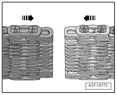
• Due to design, the distance of the chain links to each other is different - arrow -.
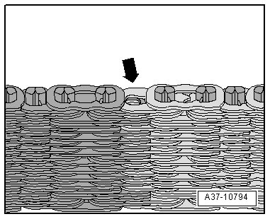
- Install both halves of the chain bolt - 1 - and - 2 - from the top, as illustrated.
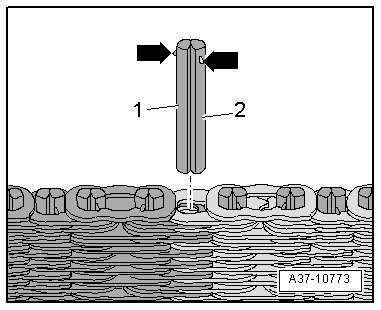
• The welding points - arrows - face upward.
• The broken off welding points on the chain bolt face downward.
• Both halves of the chain bolt are formed asymmetrical.
- Loosen knurled-head screw and push the hook opposite direction of - arrow - toward the outside.
- Remove pressure air hose - 2 - for tire valve from the retaining device (T40130/2).
- Bleed retaining device (T40130/2) via pressure air valve.
• The valve need on the pressure air valve must pushed down using a small screwdriver.
• The disc set closes, the chain tensions itself.
- Install oil guide piece "II" - arrow -.
- Install oil guide piece "I" - 1 -.
• The retaining bolts - arrows - must engage into the holes in the transmission housing.
- Install thrust washer - 1 - on disc set "I " - 3 - according to the marking made during removal.
- If equipped, install the spacer - 2 -. Note the installation position, as illustrated.
• If, in the disc set "I" a spacer - 2 - was installed, then it can be installed again if the former bearing "D" with inner race was not replaced. For bearing "D" without an inner race, a spacer cannot be installed.
CAUTION!
Danger of interchanging.
• Be sure not to interchange the thrust washer - 1 - with the shim => [ (Item 12) Adjustment shim ] Chain and Disc Set I Assembly Overview under the circlip.
- Remove intermediate housing seal - 1 -.
- Make sure alignment sleeves - 2 and 3 - are installed, if necessary install them.
- Install intermediate housing.
- Install bolts - arrow - for the intermediate housing and tighten in diagonal sequence and in stages.
• Depending on the version, the bolts can have different lengths.
• If the same disc set "I" was installed again, then the original shim and a new circlip - with the same strength and the old circlip - are installed.
- Rotate the transmission housing on the engine/transmission support, so that the disc set "I" contacts the intermediate housing by its own weight.
• The circlip - 3 - fits into the groove on the shaft and the bearing does not get damaged when the sensor wheel "I" is not installed.
- Install marked shim - 2 - onto the shaft for the disc set "I" - 1 -.
- Install new circlip - 3 - into the groove on the shaft for the disc set and press it in.
• Observe installed location: The bores in the circlips eyes are conical. The narrow side points up
• The circlip must contact the base of the groove.
• The following illustrates the intermediate housing facing upward opposite the transmission bearing.
• Always replace the sensor wheels "I" and "II".
- Carefully tap the new sensor wheel "I" and sleeve (T40131) with a rubber hammer all the way in - arrow -.
- Carefully tap new sensor wheel "II" and sleeve (3241) with a rubber hammer all the way in.
- Turn the transmission on the engine/transmission support so that the intermediate housing faces upward once again.
- Install oil pipe - arrow - by hand.
• Do not use any tools otherwise the sealing surfaces will be damaged.
- Install cover - arrow - for sensor wheel " II".
• Locating tab on rear side of cover must be inserted into small hole on transmission surface.
- Install hydraulic control unit => [ Hydraulic Control Module ] Service and Repair.
- Install Transmission Control Module (TCM) (J217 )=> [ Transmission Control Module ] Service and Repair.
- Install cover.
- Install transmission.