Output Diagnostic Test Mode
Output Diagnostic Test Mode
• The Output Diagnostic Test Mode (DTM) (shown as Final Control Diagnosis on scan tool) can only be performed with the engine stopped and the ignition switched on.
• During actuator diagnosis, the individual actuators (with the exception of the injectors) are operated in turn for about one minute unless the next actuator is selected by pressing the > button.
• The control elements can be checked acoustically or by way of touch.
• Output (DTM) is aborted if it is not switched further after one minute of activation time, the engine is started or an RPM signal is recognized.
• Before restarting the (DTM) the engine must be started and the ignition switched off and on again.
Vehicles with control module No. 8E0 909...
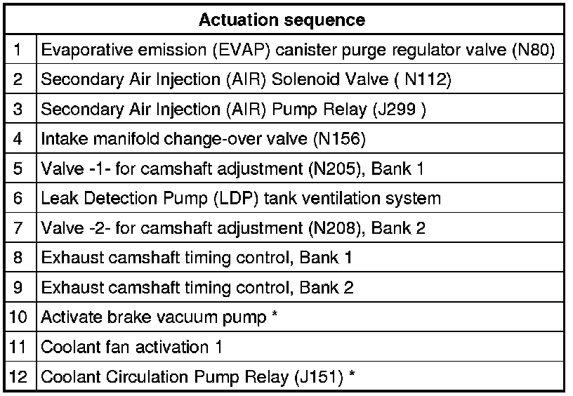
* Only on vehicles with automatic transmission.
* Only in vehicles with hot-country function.
Test requirements:
• Fuses for engine electronics OK
Test sequence
- Connect vehicle diagnostic, testing and information system (VAS5051) and select vehicle system "01 -Engine electronics" in selection. Ignition must be switched on.
Display on (VAS5051):
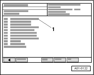
- Under - 1 - select diagnostic function "03 - Final control diagnosis".
Actuating evaporative emission (EVAP) canister purge regulator valve (tank breather valve)
Display on (VAS5051):
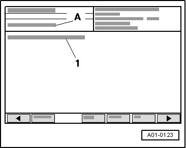
A Control element test waiting: Select next step to continue
1 Evaporative Emission (EVAP) Canister Purge Regulator Valve (N80)
- Press > button.
Display on (VAS5051):
A - Control element test running: Continuation permitted
• This valve is activated (clicks) for approx. 1 minute if the operation is not switched to the next control element by pressing the > button.
• Fuel pump must run during activation time, the flow noise at fuel pressure regulator must be clearly audible. If fuel pump does not run, check activation => [ Checking activation of fuel
pump relay ] Fuel Pump Relay and Activation, Checking.
If the valve is not actuated (does not click).
- Check solenoid valve 1 for Evaporative Emission (EVAP) Canister Purge Regulator Valve (N80). Refer to => [ EVAP Canister Purge Regulator Valve, Checking ] Testing and Inspection.
Actuating secondary air injection solenoid valve
- Press > button.
Display on (VAS5051):
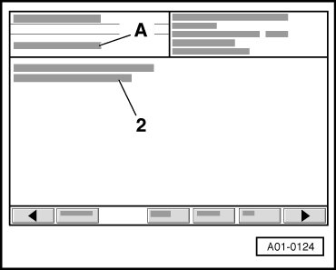
A Control element test waiting: Select next step to continue
2 Secondary Air Injection (AIR) solenoid valve (N112)
- Press > button again.
Display on (VAS5051):
A - Control element test running: Continuation permitted
• This valve is activated (clicks) for approx. 1 minute if the operation is not switched to the next control element by pressing the > button.
If the valve is not actuated (does not click).
- Check Secondary Air Injection (AIR) solenoid valve (N112).
Actuating secondary air injection pump relay
- Press > button.
Display on (VAS5051):
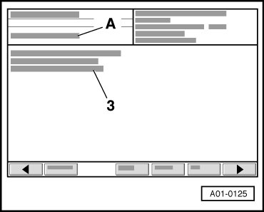
A Control element test waiting: Select next step to continue
3 Secondary Air Injection (AIR) Pump Relay (J299)
- Press > button again.
Display on (VAS5051):
A - Control element test running: Continuation permitted
• The secondary AIR pump relay (J299) (in relay carrier in electronics box, plenum chamber, position 3) switches the engine for the Secondary Air Injection (AIR) pump motor ( V101) on and off at approx. 1 minute intervals if the operation has not been switched to the next control element by pressing the > button.
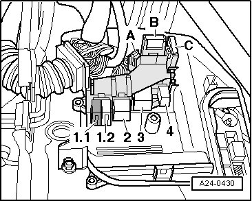
If secondary air pump does not run intermittently:
- Check Secondary Air Injection (AIR) pump relay ( J299).
Actuation of intake manifold change-over valve
- Press > button.
Display on (VAS5051):
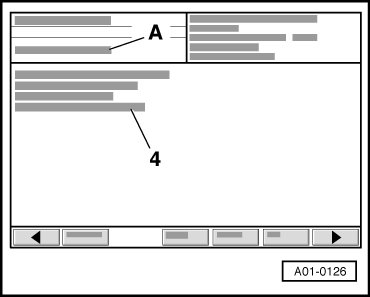
A Control element test waiting: Select next step to continue
4 Intake manifold change-over valve (N156)
- Press > button again.
Display on (VAS5051):
A - Control element test running: Continuation permitted
• This valve is activated (clicks) for approx. 1 minute if the operation is not switched to the next control element by pressing the > button.
If the valve is not actuated (does not click).
- Check intake manifold change-over valve (N156 ). Refer to => [ Intake Manifold Change-Over ] Intake Manifold Change-Over.
Actuating intake camshaft adjustment valve, Bank 1
- Press > button.
Display on (VAS5051):
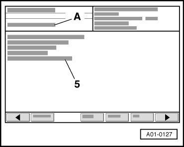
A Control element test waiting: Select next step to continue
5 Bank 1, Valve -1- for camshaft adjustment (N205)
- Press > button again.
Display on (VAS5051):
A - Control element test running: Continuation permitted
• This valve is activated (clicks) for approx. 1 minute if the operation is not switched to the next control element by pressing the > button.
If the valve is not actuated (does not click).
- Check camshaft adjustment valves.
Activating Leak Detection Pump (LDP) tank ventilation system
- Click on > button
Display on (VAS5051):
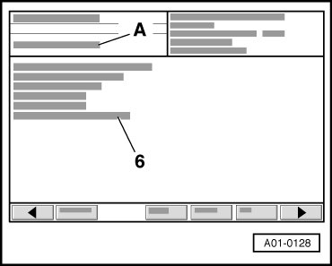
A Control element test waiting: Select next step to continue
6 Leak Detection Pump (LDP) tank ventilation system
- Click on > button again.
Display on (VAS5051):
A - Control element test running: Continuation permitted
• The Leak Detection Pump (LDP) (V144) is activated in intervals for approx. 1 minute (clicks), unless the > button is pressed first to switch to the next actuator.
• Operating noise of Leak Detection Pump (LDP) is softly audible at left rear wheelhouse.
If Leak Detection Pump (LDP) is not activated (no operating noise audible):
- Check Leak Detection Pump (LDP).
Actuating intake camshaft adjustment valve, Bank 2
- Press > button.
Display on (VAS5051):
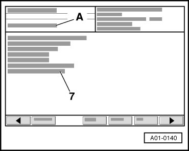
A Control element test waiting: Select next step to continue
7 Bank 2, Valve -2- for camshaft adjustment (N208)
- Press > button again.
Display on (VAS5051):
A - Control element test running: Continuation permitted
• This valve is activated (clicks) for approx. 1 minute if the operation is not switched to the next control element by pressing the > button.
If the valve is not actuated (does not click).
- Check camshaft adjustment valves.
Actuating exhaust camshaft adjustment valve, Bank 1
- Press > button.
Display on (VAS5051):
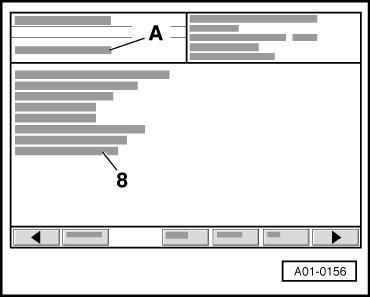
A Control element test waiting: Select next step to continue
8 Bank 1, camshaft adjustment (exhaust)
- Press > button again.
Display on (VAS5051):
A - Control element test running: Continuation permitted
• This valve is activated (clicks) for approx. 1 minute if the operation is not switched to the next control element by pressing the > button.
If the valve is not actuated (does not click).
- Check camshaft adjustment valves:
Actuating exhaust camshaft adjustment valve, Bank 2
- Press > button.
Display on (VAS5051):
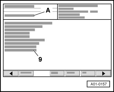
A Control element test waiting: Select next step to continue
9 Bank 2, camshaft adjustment (exhaust)
- Press > button again.
Display on (VAS5051):
A - Control element test running: Continuation permitted
• This valve is activated (clicks) for approx. 1 minute if the operation is not switched to the next control element by pressing the > button.
If the valve is not actuated (does not click).
- Check camshaft adjustment valves.
Actuating brake vacuum pump *
* Only on vehicles with automatic transmission.
- Press > button.
Display on (VAS5051):
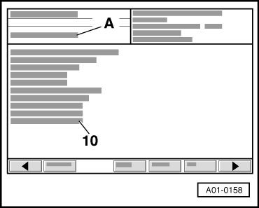
A Control element test waiting: Select next step to continue
10 Activation of brake vacuum pump
- Press > button again.
Display on (VAS5051):
A - Control element test running: Continuation permitted
• The brake servo vacuum pump, left front in engine compartment, must start up for a short time, unless the operation has been switched to the next control element by pressing the > button.
If the brake servo vacuum pump does not start up:
- Check brake servo vacuum pump.
Actuating coolant fan control
- Press > button.
Display on (VAS5051):
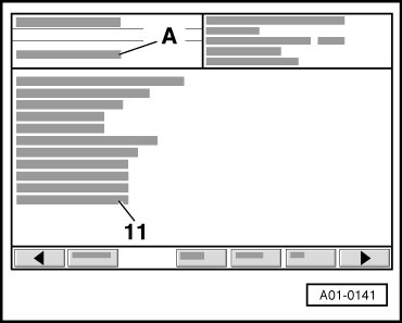
A Control element test waiting: Select next step to continue
11 Coolant FC (Fan Control) activation 1
- Press > button again.
Display on (VAS5051):
A - Control element test running: Continuation permitted
• Coolant FC (Fan Control) Control Module (J293) (top right on fan frame - arrow -) slowly regulates coolant fan once up to maximum RPM, unless the > button is pressed first, to switch to the next actuator.
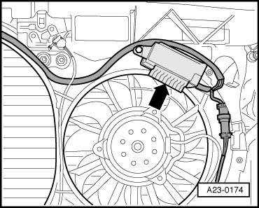
If the fan does not start:
- Check coolant fan and Coolant FC (Fan Control) Control Module (J293). Refer to
Actuating relay for coolant run-on pump *
* only in vehicles with hot-country function
- Press > button.
Display on (VAS5051):
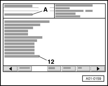
A Control element test waiting: Select next step to continue
12 Coolant Circulation Pump Relay (J151)
- Press > button again.
Display on (VAS5051):
A - Control element test running: Continuation permitted
• The Coolant Circulation Pump Relay (J151) switches the pump for coolant run-on on and off at one minute intervals unless the > button is first pressed to switch to the next control element.
If the after-run coolant pump does not start:
- Check whether hot-country function is coded. Refer to => [ Coding II Login Procedure ] Coding II Login Procedure.
Actuating injectors
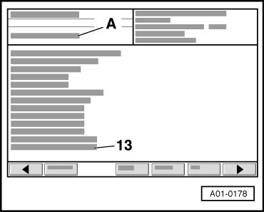
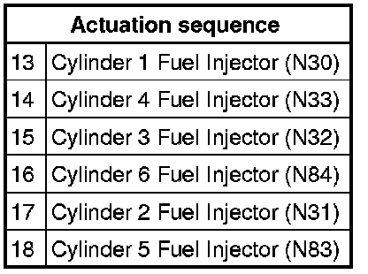
• The injectors are actuated according to the ignition sequence: cyl. 1, cyl. 4, cyl. 3, cyl. 6, cyl. 2, cyl. 5.
- Press > button.
A Control element test waiting: Select next step to continue
13 Cylinder 1 Fuel Injector ( N30)
- Press > button again.
Display on (VAS5051):
A - Control element test running: Continuation permitted
• After pressing the > button the injector must click five times.
- Use this procedure to check all injectors in sequence.
If one of the injectors is not actuated (does not click):
- Test injectors. Refer to => [ Fuel Injectors, Checking ] Fuel Injectors, Checking.
- After activating last injector (cylinder 5) press > button.
Display on (VAS5051):
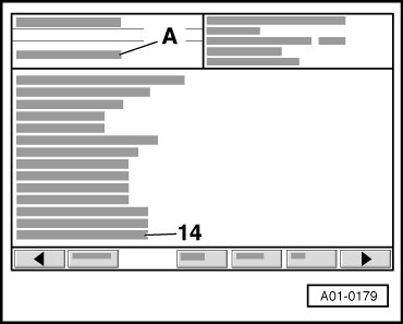
A Control element test waiting: Select next step to continue
14 Cylinder 4 Fuel Injector ( N33)
- Click on > button again.
Display on (VAS5051):
A - Control element test running: Continuation permitted
• Fuel injector must click 5 times after > button is pressed.
- Click on > button
Display on (VAS5051):
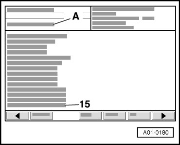
A Control element test waiting: Select next step to continue
15 Cylinder 3 Fuel Injector ( N32)
- Click on > button again.
Display on (VAS5051):
A - Control element test running: Continuation permitted
• Fuel injector must click 5 times after > button is pressed.
- Click on > button
Display on (VAS5051):
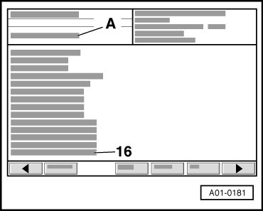
A Control element test waiting: Select next step to continue
16 Cylinder 6 Fuel Injector ( N84)
- Click on > button again.
Display on (VAS5051):
A - Control element test running: Continuation permitted
• Fuel injector must click 5 times after > button is pressed.
- Click on > button
Display on (VAS5051):
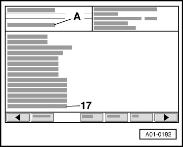
A Control element test waiting: Select next step to continue
17 Cylinder 2 Fuel Injector ( N31)
- Click on > button again.
Display on (VAS5051):
A - Control element test running: Continuation permitted
• Fuel injector must click 5 times after > button is pressed.
- Click on > button
Display on (VAS5051):
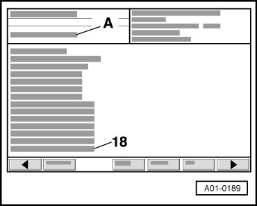
A Control element test waiting: Select next step to continue
18 Cylinder 5 Fuel Injector ( N83)
- Click on > button again.
Display on (VAS5051):
A - Control element test running: Continuation permitted
• Fuel injector must click 5 times after > button is pressed.
If one of the fuel injectors is not activated (does not click).
- Check fuel injectors. Refer to => [ Fuel Injectors, Checking ] Fuel Injectors, Checking.
- Click on > button
Display on (VAS5051):
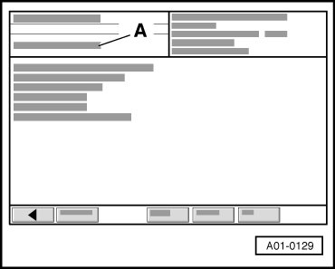
A - control element test is completed
- Exit function "03 - Final control diagnosis" by pressing arrow button.
• Before restarting the Output Diagnosis Test Mode (DTM) the engine must be started and the ignition switched off and on again.