A/C Unit
A/C Unit
Special Tools and Equipment
• Hose Clamps (3093 bzw. 3094)
• Cooling System Tester (V.A.G 1274)
• Compressed air gun, commercially available
Removing
• On removal, note down bolt lengths and assignment for reinstallation.
• All cable ties and other wiring harness fasteners released or cut open on removing air conditioner unit are to be re-attached in same position on installation.
- Drain the refrigerant circuit: => Refrigerant R134a - Servicing
- Switch ignition on.
- Move power seats to rearmost position.
- Switch off ignition.
- Remove dust and pollen filter. Refer to=> [ Dust and Pollen Filter ] .
- Remove E-box cover and engine control module.
- Remove dome brace with reinforcement to cowl panel trim.
- Remove windshield wiper completely.
- Remove pump valve unit. Refer to=> [ Pump Valve Unit, Checking ] Pump Valve Unit, Checking.
- Protect driver and passenger seat using seat cover.
- Disconnect negative terminal clamp from Battery (A).
• Before disconnecting Battery (A), obtain anti-theft radio security code if necessary.
• On vehicles with electrically adjustable seats, move the seats back as far as possible before disconnecting the Battery (A).
- Remove dash panel complete with dash panel cross member.
- Remove brake master cylinder and brake booster.
- Remove complete foot pedal assembly with mounting bracket.
- Disconnect refrigerant lines from evaporator connection. Refer to => [ Refrigerant Lines, Disconnecting and Connecting from Evaporator ] Removal and Replacement.
- Remove Rotation Rate Sensor (G202).
- Remove brackets - A - and - B - depending on A/C unit version, only brackets - B - or - A - are installed.
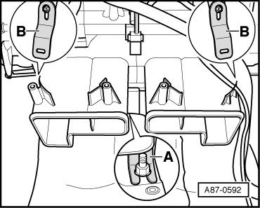
- Remove air guides to footwell vents.
- Disconnect condensation drain hoses from heating and A/C unit. Refer to => [ Condensate Drain Hose ] Description and Operation.
- Disconnect harness connectors to heating and A/C unit.
- Remove bolts - A -.
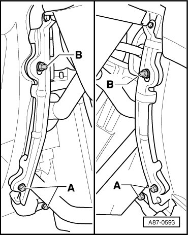
- Remove bolts - B -.
- Remove A/C unit toward vehicle interior.
Installing
Installation is carried out in the reverse order, when doing this note the following:
- Replace seal - A - between plenum chamber and A/C unit.
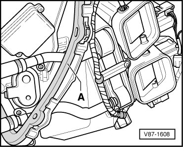
• Check other seals and replace them if necessary.
• Connect coolant hoses to heater core accurate to side. Refer to => [ Pump Valve Unit, Checking ] Pump Valve Unit, Checking.
• Secure all hose connections with standard hose clamps or clips as used in series production, or approved replacement parts.
• When inserting A/C unit, make sure that wiring to actuators in plenum chamber and seal - A - is not jammed or damaged by studs.
- Check damper element - C - for proper seating.
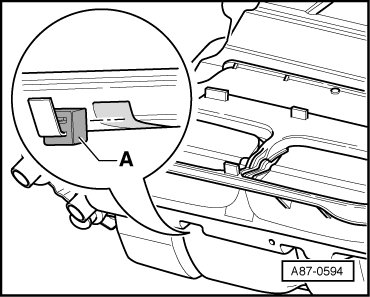
- After installation, check grommet between engine compartment and plenum chamber for proper seating.
- Seal 4 bolts - A - left and right in plenum chamber using Terolan (D 511 500 A2).
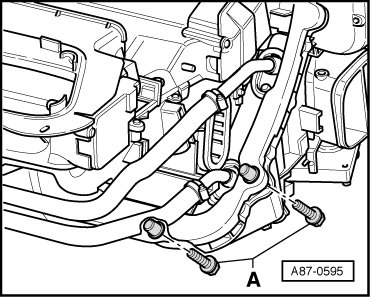
- Check the condensation drain hoses for proper seating. Refer to => [ Condensate Drain Hose ] Description and Operation.
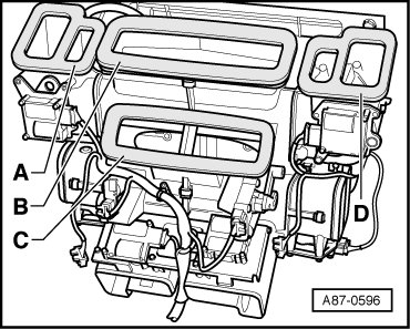
- Before installing instrument panel, check foam seals - A - to - D -, replace damaged seals if necessary.
- Install removed components, except driver's storage compartment and glove compartment, in reverse order.
- Check coolant hoses to heater cores are secured. Refer to => [ Left Heat Exchanger ] Service and Repair.
- Bleed coolant circuit, connect 2-pin harness connector to pump valve unit only after bleeding coolant circuit. Refer to => [ Pump Valve Unit, Checking ] Pump Valve Unit, Checking
- Before installing driver's storage compartment and glove compartment, check cooling system for leaks, paying particular attention to connection between coolant pipes and heater cores. Refer to => [ Left Heat Exchanger ] Service and Repair.
- Install glove compartment, driver's storage compartment and remaining components removed.
- Evacuate and re-charge refrigerant circuit. => Refrigerant R134a - Servicing
- Check the DTC memory for the Rear A/C Control Module (Climatronic) (E265) and the Climatronic Control Module (J255) front A/C control head and erase any stored DTCs vehicle diagnosis, testing and information system VAS 5051 in the "Guided Fault Finding" function.
- Perform a basic setting and output diagnostic test mode on the A/C system vehicle diagnosis, testing and information system VAS 5051 in the "Guided Fault Finding" function.
- Operate the A/C system after filling the refrigerant circuit. Refer to=> [ Operating A/C System after Filling Refrigerant Circuit ] Operating A/C System after Filling Refrigerant Circuit
• Note the information regarding operating the A/C system after filling => Refrigerant R134a - Servicing.