Torque Support With Torque Support Valve
Torque Support with Torque Support Valve
Removing
Special tools, testers and auxiliary items required
• Drill
• Stepped quick helix drill bit (24 mm diameter)
• Before raising the vehicle on the hoist (wheels off the ground), activate the vehicle left mode.
- Turn the ignition and remove the ignition key.
- Turn the light switch to "0" position.
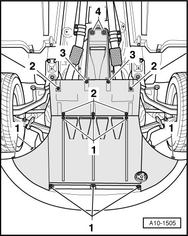
- Remove the front noise insulation fasteners - 1 - and noise insulation.
- Remove the front part of the wheel housing liner at the left and right front.
- Remove the front bumper cover.
- Remove the clips - 1 -.
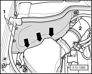
- Remove the bolt - 2 - and remove the cover.
• Note the clips - arrows - when installing.
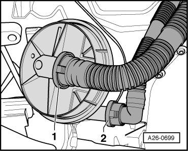
- Disconnect the intake air duct - 1 - from the Secondary Air Injection (AIR) pump.
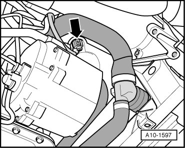
- Disconnect the electrical connector - arrow -.
- Disconnect the electrical connector - 1 - from Mass Air Flow (MAF) sensor.
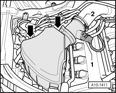
- Loosen the clamp - 2 - and remove the MAF sensor from intake air duct.
- Remove the air filter box screws - arrows -.
- Remove the right headlamp.
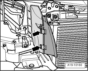
- Press the locking mechanisms - arrows - and remove the air guide from the lock carrier at the right front.
- Remove the bolts - arrows -.
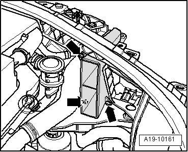
- Remove the air guide from the lock carrier at the right rear.
- Mark the holes according to dimensions - a and b - at the lock carrier as shown.
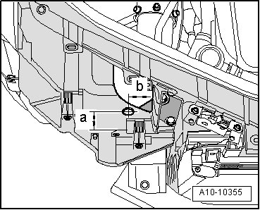
• Dimension - a - = 40 mm.
• Dimension - b - = 55 mm
- Make a 24 mm diameter hole.
• The hole must be pre-bored and then drilled to 24 mm using the stepped quick helix drill bit.
- Unclip the cable clips - arrows -.
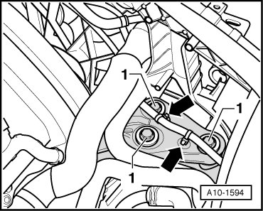
- Remove the bolts - 1 and 2 - for the torque support.
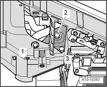
- Loosen the bolt - 3 - several turns.
- Remove the torque support bolt - arrow - from the torque support valve (N382).
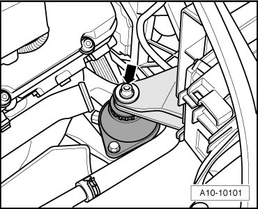
- Remove the bolts - 2 and 3 -.
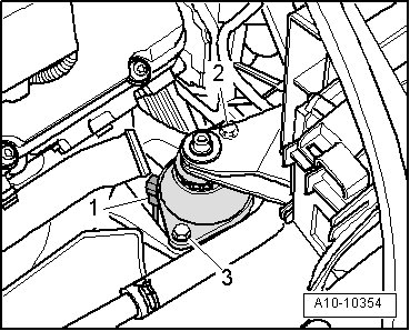
- Swivel the torque support aside and disconnect the electrical connector - 1 -.
- Remove the torque support valve.
Installing
Installation is performed in the reverse order of removal, noting the following:
• All cable ties which are opened or cut off when removing the engine, must be replaced in the same position when installing the engine.
• Secure all hose connections using hose clamps appropriate for the model type.
- Connect the electrical connector - 1 - to the torque support valve.
- Install the torque support valve and tighten bolts - 2 and 3 -.
- Turn the knurled nut - 1 - on the torque support valve clockwise until the stop.
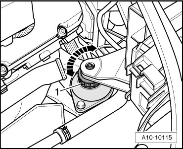
- Tighten bolts - 1 and 3 - for the torque support.
- Turn the knurled nut - 1 - by hand counterclockwise until it makes contact at the torque support valve.
- Then, turn the knurled nut one rotation clockwise again.
- Tighten the bolt - arrow - for the torque support valve.
- Clip in the cable clips - arrows -.
- Install the headlamps.
- Install the front bumper cover.
- .
Tightening Specifications
Tightening specifications, refer to => [ Torque Bracket and Support Valve Assembly Overview ] Torque Bracket and Support Valve Assembly Overview.