Lock Carrier With Attachments Assembly Overview
Lock Carrier with Attachments Assembly Overview
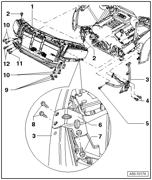
1 - Lock Carrier
• Removal:
• Front section of front wheel housing liner removed, refer to => [ Front Wheel Housing Liner Front Section ] Wheel Housing Liner.
• Bumper cover, removing, refer to => [ Bumper Cover ] Service and Repair.
• Disengage release for hood lock, refer to => [ Hood Release Cable Assembly Overview ] Service and Repair.
• Remove intake air duct between lock carrier and air cleaner housing at lock carrier.
• Before removing, disconnect all electrical harness connectors.
• Disconnect coolant lines and drain coolant. refer to => [ Drain Coolant Circuit ].
• Fill with coolant and bleed the system.
• Discharge A/C refrigerant system
• Disconnect refrigerant lines from the bottom of the condenser. Refer to => [ Condenser Refrigerant Lines Disconnecting and Connecting ] Condenser Refrigerant Lines, Connecting and Disconnecting
• Disconnect hoses leading to the power steering oil cooler at the bottom of the condenser, refer to => [ Condenser Refrigerant Lines Disconnecting and Connecting ] Condenser Refrigerant Lines, Connecting and Disconnecting.
• Disconnect hose for air guide.
• Pull off gasket for left and right front flap at juncture of fender at lock carrier - 1 -.
• Remove the bolts - 2 -;- 7 - - 9 - and - 10 -.
• The bolt - 7 - is installed behind the front wheel housing liner front part.
• Remove the nut from the banjo bolt at the top of the fender, refer to => [ Securing Lock Carrier/Fender ].
• Pull lock carrier off toward front.
• Installing:
• in reverse order
• The headlamps must be set.
• Adjusting:
• A second technician will be needed to hold the lock carrier - 1 -.
• Lock carrier - 1 - must be aligned between the fenders.
• When fenders and front bumper are replaced, they must adjusted in conjunction with lock carrier.
2 - Bolt
• 23 Nm
3 - Front Brace
• Installation position, refer to => [ Front Brace Assembly Overview ] Front Brace Assembly Overview
4 - Bolt
• 25 Nm
5 - Bolt
• 30 Nm
6 - Front Brace Bracket
7 - Bolt
• 23 Nm
• Installation position, refer to => [ Front Brace Assembly Overview ] Front Brace Assembly Overview.
8 - Bolt
• 10 Nm
9 - Nut
• 30 Nm
• Installed only on the Audi S8.
• 30 Nm
10 - Bolt
• M8 • 40 mm
• 30 Nm
11 - Bolt
• M8 • 30 mm
Securing Lock Carrier/Fender
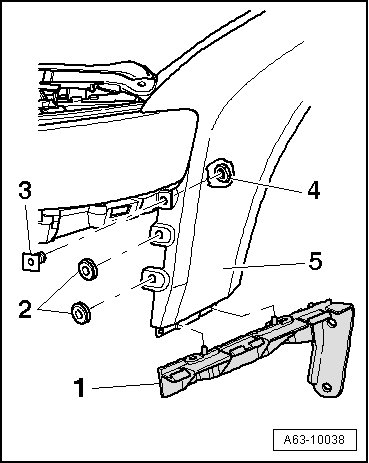
- Remove the nut - 4 - from the banjo bolt - 3 -.
- Tighten the nut to 5 Nm when installing.
Drain Coolant Circuit
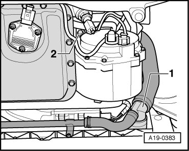
- Place the (VAS 6208) under the engine.
- Disconnect coolant hose - 1 - to drain coolant.
- Drain refrigerant circuit.